Sanyo CL4232 User Manual
Browse online or download User Manual for Conditioners Sanyo CL4232. Sanyo CL4232 User Manual
- Page / 66
- Table of contents
- BOOKMARKS
Rated. / 5. Based on customer reviews
85464869178000 REFERENCE NO. SM830078
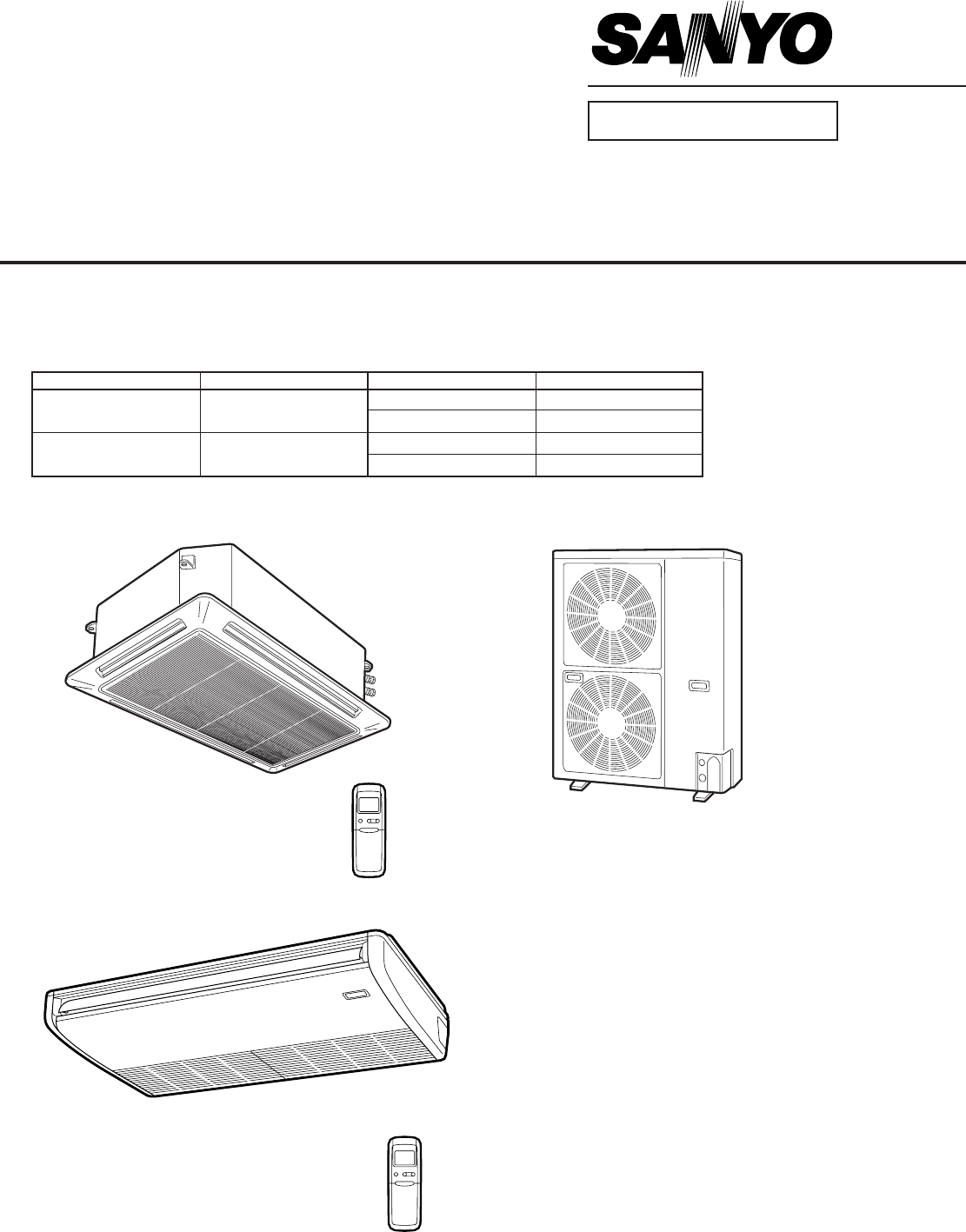
SPLIT SYSTEM AIR CONDITIONER
TECHNICAL DATA
&
SERVICE MANUAL
FILE NO.
INDOOR MODEL No. PRODUCT CODE No. OUTDOOR MODEL No. PRODUCT CODE No.
XS4232 854 016 10
C4232 854 016 12
CL4232 854 016 11
TS4232 854 016 09
C4232 854 016 12
CL4232 854 016 11
TS4232
XS4232 C4232
CL4232
Indoor Unit Outdoor Unit
XS4232 / C4232, CL4232
TS4232 / C4232, CL4232
- TECHNICAL DATA 1
- SERVICE MANUAL 1
- Important 2
- Table of Contents 3
- Read Me First! 4
- 1. OPERATING RANGE 5
- 2. SPECIFICATIONS 10
- 3. DIMENSIONAL DATA 18
- 4. COOLING CAPACITY 21
- 5. PERFORMANCE CHARTS 25
- VERTICAL DISTANCE (ft.) 31
- AXIS AIR VELOCITY (ft./sec) 31
- 7. REFRIGERANT FLOW DIAGRAM 32
- 8. INSTALLATION INSTRUCTIONS 33
- 9. ELECTRICAL DATA 38
- • Electric Wiring Diagram 39
- • Schematic Diagram 40
- 11. PROCESSES AND FUNCTIONS 47
- 47 50 59 63 77 81 49
- 12. SERVICE PROCEDURES 50
- 0631_X_S 57
- 0630_X_S 57
- 0638_X_S 62
- 0642_X_S 63
- Temperature (°F) 65
- SANYO FISHER Service Company 66
- CENTRAL REGION 66
Summary of Contents
Page 1 - SERVICE MANUAL
85464869178000 REFERENCE NO. SM830078SPLIT SYSTEM AIR CONDITIONERTECHNICAL DATA&SERVICE MANUALFILE NO. INDOOR MODEL No. PRODUCT CODE No. OUTDOOR
Page 2 - Important
– 10 –SM830078(2) Major Component Specifications(A) Indoor Unit2. SPECIFICATIONSDATA SUBJECT TO CHANGE WITHOUT NOTICEMODEL No. XS4232Source 230 - 208
Page 3 - Table of Contents
– 11 –SM830078(2) Major Component Specifications(A) Indoor Unit2. SPECIFICATIONSMODEL No. TS4232Source 230 - 208 V / 1 phase / 60 HzRemote controlle
Page 4 - Read Me First!
– 12 –SM830078(2) Major Component Specifications(B) Outdoor Unit2. SPECIFICATIONS+ 2.0+ 0.5DATA SUBJECT TO CHANGE WITHOUT NOTICEMODEL No. C4232Source
Page 5 - 1. OPERATING RANGE
– 13 –SM8300782. SPECIFICATIONS(2) Major Component Specifications(B) Outdoor UnitMODEL No. CL4232Source 230 - 208 V / 1 phase / 60 HzController P.C.B
Page 6
– 14 –SM8300782. SPECIFICATIONS(3) Other Component Specifications(A) Indoor UnitMODEL No. XS4232Power Transformer ATR – I104ARated Primary AC 220 V, 6
Page 7
– 15 –SM8300782. SPECIFICATIONS(3) Other Component Specifications(A) Indoor UnitMODEL No. TS4232Power Transformer ATR – I104ARated Primary AC 220 V,
Page 8
– 16 –SM830078(3) Other Component Specifications(B) Outdoor UnitMODEL No. C4232Compressor Motor Magnetic Contactor FC - 2SULCoil rated AC 240 V, 60 Hz
Page 9
– 17 –SM830078(3) Other Component Specifications(B) Outdoor UnitMODEL No. CL4232Compressor Motor Magnetic Contactor FC - 2SULCoil rated AC 240 V, 60
Page 10 - 2. SPECIFICATIONS
– 18 –SM8300783. DIMENSIONAL DATA(1) Indoor Unit: XS423245-9/3241-11/3231-3/3219-11/1612-29/321-3/168-19/324-29/3233-27/3243-11/16 (Ceiling opening)32
Page 11
– 19 –SM8300783. DIMENSIONAL DATA(1) Indoor Unit: TS4232Drain connectionDrain connection for left sideRefrigerant liquid line (3/8") Flare conne
Page 12
– 2 –SM830078Please Read Before StartingThis air conditioning system meets strict safety and operatingstandards. As the installer or service person, i
Page 13
– 20 –SM8300783. DIMENSIONAL DATA(2) Outdoor Unit: C4232, CL423248-5/822-27/3223-29/3237Dimension : inchHole for anchor bolt (4-ø13)Refrigerant tube j
Page 14
– 21 –SM8300784. COOLING CAPACITYRATING CAPACITY : 42,000 BTU / h AIR FLOW RATE : 980 CFMEVAPORATOR CONDENSERENT. TEMP. °F (°C) AMBIENT TEMP. °F (°
Page 15
– 22 –SM8300784. COOLING CAPACITY11111 Indoor Unit: XS4232 Outdoor Unit: C4232, CL4232• 208V / 1 phase / 60HzRATING CAPACITY : 40,500 BTU / h AIR FLO
Page 16
– 23 –SM8300784. COOLING CAPACITYRATING CAPACITY : 42,000 BTU / h AIR FLOW RATE : 900 CFMEVAPORATOR CONDENSERENT. TEMP. °F (°C) AMBIENT TEMP. °F (°
Page 17
– 24 –SM8300784. COOLING CAPACITY22222 Indoor Unit: TS4232 Outdoor Unit: C4232, CL4232• 208V / 1 phase / 60HzRATING CAPACITY : 40,500 BTU / h AIR FLO
Page 18 - 3. DIMENSIONAL DATA
– 25 –SM8300785. PERFORMANCE CHARTS(1) Operating Current11111 Indoor Unit: XS4232 Outdoor Unit: C4232Operating current characteristics versus outdoor
Page 19
– 26 –SM8300785. PERFORMANCE CHARTS(1) Operating Current22222 Indoor Unit: TS4232 Outdoor Unit: C4232Operating current characteristics versus outdoor
Page 20
– 27 –SM8300785. PERFORMANCE CHARTS(1) Operating Current33333 Indoor Unit: XS4232 Outdoor Unit: CL4232Operating current characteristics versus outdoo
Page 21 - 4. COOLING CAPACITY
– 28 –SM8300785. PERFORMANCE CHARTS(1) Operating Current44444 Indoor Unit: TS4232 Outdoor Unit: CL4232Operating current characteristics versus outdoor
Page 22
– 29 –SM8300785. PERFORMANCE CHARTS(2) High and Low Pressure11111 Indoor Unit: XS4232, TS4232 Outdoor Unit: C4232 • High PressureHigh pressure charac
Page 23
– 3 –SM830078Table of Contents1. OPERATING RANGE ... 52. SPECIFIC
Page 24
– 30 –SM8300785. PERFORMANCE CHARTS(2) High and Low Pressure22222 Indoor Unit: XS4232, TS4232 Outdoor Unit: CL4232 • High PressureHigh pressure charac
Page 25 - 5. PERFORMANCE CHARTS
– 31 –SM8300786. AIR THROW DISTANCE CHARTMODEL: XS423203 7 101317200371013HORIZONTAL DISTANCE (ft.)AXIS AIR VELOCITY (ft./sec)VERTICAL DISTANCE (ft.)
Page 26
– 32 –SM8300787. REFRIGERANT FLOW DIAGRAMIndoor Unit: 4232 Type Outdoor Unit: C4232, CL4232O. D.3/4"(19.05 mm)EvaporatorCapillaryO. D.3/8"(9
Page 27
– 33 –SM8300788. INSTALLATION INSTRUCTIONS1) Tubing Length• Refrigerant tubing between the indoor andoutdoor units should be kept as short aspossible
Page 28
– 34 –SM8300788. INSTALLATION INSTRUCTIONS2) Selecting the Installation SiteAVOID:ã areas where leakage of flammable gas maybe expected.ã places where
Page 29
– 35 –SM8300788. INSTALLATION INSTRUCTIONSOut-doorunitHeat sourceHot airExhaust fan0591_C_IFig. 2Fig. 3Min.1 inchMin.1 inchMin. 2 ft.4 in.0931_C_IMin
Page 30
– 36 –SM8300788. INSTALLATION INSTRUCTIONSAir Discharge Chamber for Top DischargeInstall the air-discharge chamber in the field when:ã it is difficult
Page 31 - AXIS AIR VELOCITY (ft./sec)
– 37 –SM8300788. INSTALLATION INSTRUCTIONS3) Electrical WiringGeneral Precautions on Wiring(1) Before wiring, confirm the rated voltageof the unit as
Page 32 - 7. REFRIGERANT FLOW DIAGRAM
– 38 –SM8300789. ELECTRICAL DATAIndoor Unit Outdoor UnitComplete UnitFan Motor Fan Motor CompressorPerformance at 230 - 208 V / 1 phase / 60 Hz 230 -
Page 33 - 8. INSTALLATION INSTRUCTIONS
– 39 –SM83007810. ELECTRICAL WIRING DIAGRAMS(1) Indoor Unit11111 XS4232TH1 (Coil)31DPConnector9P(WHT)Connector2P(YEL)31FS2131313175315213213SP1231231
Page 34
– 4 –SM830078Introduction: Read Me First!This manual will help you understand and service the air conditioner. To help you find the information you ne
Page 35
– 40 –SM83007810. ELECTRICAL WIRING DIAGRAMS(1) Indoor Unit11111 XS4232• Schematic DiagramS 854-2-5268-578-00-0 (XS3632)2131312IND3127171SWTR1PRYCoilT
Page 36
– 41 –SM830078(1) Indoor Unit22222 TS423210. ELECTRICAL WIRING DIAGRAMSTH1 (Coil)31Connector9P(WHT)Connector2P(YEL)312131313175315213213Connector2P(B
Page 37
– 42 –SM83007810. ELECTRICAL WIRING DIAGRAMS(1) Indoor Unit22222 TS4232• Schematic DiagramS 854-2-5268-593-00-0 (TS3632)2131312IND3127171SWTR1PRYCoilT
Page 38 - 9. ELECTRICAL DATA
– 43 –SM83007810. ELECTRICAL WIRING DIAGRAMS(2) Outdoor Unit11111 C4232• Electric Wiring DiagramW 854-2-5268-896-00-0 (C4232)PSFMO2RC349FO2RC1BLUBLKP
Page 39 - • Electric Wiring Diagram
– 44 –SM83007810. ELECTRICAL WIRING DIAGRAMS(2) Outdoor Unit11111 C4232SVRUCLRC1SCR52CH23S1YCMRC2FMO13151Y652 1RC3FMO2426652 134349FO1Terminal Plate (
Page 40 - • Schematic Diagram
– 45 –SM83007810. ELECTRICAL WIRING DIAGRAMS(2) Outdoor Unit22222 CL4232L1L2124GL1L2TerminalPlate (6P)Power Supply60Hz 1PH 208 V / 230 VTo Indoor Uni
Page 41
– 46 –SM83007810. ELECTRICAL WIRING DIAGRAMS(2) Outdoor Unit22222 CL4232• Schematic Diagram132121TRAC 208V230VAC 14VTHOutdoor TemperatureCM52CCRUSVSRR
Page 42
– 47 –SM83007811. PROCESSES AND FUNCTIONSFig. 8(1) Room Temperature ControlThe Unit adjusts room temperature by turning the outdoor unit’s compressor
Page 43
– 48 –SM83007811. PROCESSES AND FUNCTIONS(2) Freeze PreventionFreeze Prevention keeps the indoor heat exchange coil from freezing. Freezing reduces th
Page 44
– 49 –SM83007811. PROCESSES AND FUNCTIONS(4) Outdoor Fan Speed Control1) C4232 Type• In low outdoor temperature, the outdoor fan is set automatically
Page 45
– 5 –SM8300781. OPERATING RANGEXS4232, TS4232 / C4232XS4232, TS4232 / CL4232Temperature Indoor Air Intake Temp. Outdoor Air Intake Temp.Maximum 95 °F
Page 46
– 50 –SM83007812. SERVICE PROCEDURESSingle-phase outdoor unit12G4124GL1L2GIndoor Unit Outdoor UnitPower supplyGroundBA1089_M_IGroundInter-UnitWiring
Page 47 - 11. PROCESSES AND FUNCTIONS
– 51 –SM83007812. SERVICE PROCEDURES2) Air Conditioner does not Operate11111 Circuit breaker trips (or fuse blows).(a) When the circuit breaker is se
Page 48
– 52 –SM83007812. SERVICE PROCEDURES(b)Circuit breaker trips in several minutes after turning the air conditioner on.• There is a possibility of short
Page 49 - 47 50 59 63 77 81
– 53 –SM83007812. SERVICE PROCEDURESC. Check “Operation selector” switch in the indoor unit.D. Check compressor motor protectors.(a) High pressure sw
Page 50 - 12. SERVICE PROCEDURES
– 54 –SM83007812. SERVICE PROCEDURESF. Check. auxiliary relay. (1Y or 2Y)H. Check fuse on the P.C.B. Ass’y in the indoor unit.G. Check indoor fan moto
Page 51
– 55 –SM83007812. SERVICE PROCEDURES3) Outdoor Unit does not Run.A. Check COOL / FAN selector switch in the remote control unit.B. Check set temperat
Page 52
– 56 –SM83007812. SERVICE PROCEDURESC. Check compressor motor magnetic contactor.F. Check float switch. (XS Type only)• Refer to “2-3 Drain Pump Contr
Page 53
– 57 –SM83007812. SERVICE PROCEDURES5) Some Part does not Operate.A. Indoor fan does not run.4) Indoor Unit does not Run.(Indoor fan and louver motor
Page 54
– 58 –SM83007812. SERVICE PROCEDURES7) Outdoor Fan Speed is not Switched from High to Low even when the OutdoorTemperature Falls below 78 °F. (C4232 T
Page 55
– 59 –SM83007812. SERVICE PROCEDURES9) Outdoor Fan does not Run for CL4232.10) Compressor does not Run.• Check fuse on PCB Ass’y in outdoor unit fo
Page 56
– 6 –SM830078(1) Unit Specifications2. SPECIFICATIONSMODEL No. Indoor Unit XS4232Outdoor Unit C4232POWER SOURCE 230 - 208 V / 1 Phase / 60 HzPERFORMAN
Page 57 - 0630_X_S
– 60 –SM83007812. SERVICE PROCEDURES11) Poor Cooling12) Excessive Cooling. Check installation position of remote control unit.• Does cool air from a
Page 58
– 61 –SM83007812. SERVICE PROCEDURES(2) A Sensor is Defective11111 Indoor (heat exchanger) coil temp. Sensor is defective.(a) Open (=No continuity in
Page 59
– 62 –SM83007812. SERVICE PROCEDURES(4) Checking the Electrical Components1) Measurement of InsulationResistance• The electrical insulation is accepta
Page 60
– 63 –SM83007812. SERVICE PROCEDURES2) Checking the Protective Devices• Disconnect the connector, which consists of P (plug) and S (socket) when you
Page 61
– 64 –SM83007812. SERVICE PROCEDURES3) Checking the Electrical Parts11111 Power transformer (TR1) ... Indoor unit *Measure the coil resi
Page 62 - 0638_X_S
– 65 –SM83007812. SERVICE PROCEDURES66666 Continuity of fuse on P.C.B. Ass’y• Check for continuity using a multimeteras shown in Fig. 19.Method Used
Page 63 - 0642_X_S
SANYO FISHER Service CompanyCENTRAL REGION1739 Sands Place, Suite GMarietta, GA 30067Phone: (770) 951-8284Fax: (770) 951-2077Jun. / ’2000 Printed in U
Page 64
– 7 –SM8300782. SPECIFICATIONS(1) Unit SpecificationsMODEL No. Indoor Unit XS4232Outdoor Unit CL4232POWER SOURCE 230 - 208 V / 1 Phase / 60 HzPERFORM
Page 65 - Temperature (°F)
– 8 –SM830078(1) Unit Specifications2. SPECIFICATIONSMODEL No. Indoor Unit TS4232Outdoor Unit C4232POWER SOURCE 230 - 208 V / 1 Phase / 60 HzPERFORMAN
Page 66 - CENTRAL REGION
– 9 –SM8300782. SPECIFICATIONS(1) Unit SpecificationsMODEL No. Indoor Unit TS4232Outdoor Unit CL4232POWER SOURCE 230 - 208 V / 1 Phase / 60 HzPERFORM
Related products and manuals for Conditioners Sanyo CL4232
 (36 pages)
Conditioners Sanyo 12KHS71 User Manual
 (2 pages)
(2 pages)
Conditioners Sanyo 12RS11 User Manual
(3 pages)
(3 pages)
Conditioners Sanyo AHX0752 User Manual
(114 pages)
(114 pages)
Conditioners Sanyo CHDZ09053 User Manual
(265 pages)
(265 pages)
Conditioners Sanyo Cool/Dry User Manual
(24 pages)
(24 pages)
Conditioners Sanyo CH2472 User Manual
(4 pages)
(4 pages)
Conditioners Sanyo 26XW72R User Manual
(2 pages)
(2 pages)
Conditioners Sanyo 26TW72R User Manual
(2 pages)
(2 pages)
Conditioners Sanyo 42TS32A User Manual
(3 pages)
(3 pages)
Conditioners Sanyo CL0971 User Manual
(4 pages)
(4 pages)
Conditioners Sanyo C3682 User Manual
(104 pages)
(104 pages)
Conditioners Sanyo 36UW72R User Manual
(2 pages)
(2 pages)
Conditioners Sanyo KHHS2672R User Manual
(4 pages)
(4 pages)
Conditioners Sanyo CM1972 User Manual
(99 pages)
(99 pages)
Conditioners Sanyo 12XLS71 User Manual
(2 pages)
(2 pages)
Conditioners Sanyo 200 BTU User Manual
(2 pages)
(2 pages)
Conditioners Sanyo CL1251 User Manual
(22 pages)
(22 pages)
© 2020, manymanuals.com. All rights reserved. | 1.615 s |
 Manymanuals.com
 Manymanuals.de
 Manymanuals.fr
 Manymanuals.it
 Manymanuals.pl
 Manymanuals.cz
 Manymanuals.es
 Manymanuals-pt.com
Comments to this Manuals