Sanyo CG1411 User Manual
Browse online or download User Manual for Heat pumps Sanyo CG1411. Sanyo CG1411 User's Manual
- Page / 100
- Table of contents
- TROUBLESHOOTING
- BOOKMARKS
- GAS HEATER AIR CONDITIONER 1
- IMPORTANT! 2
- Please Read Before Starting 2
- Table of Contents 3
- 1. OPERATING RANGE 5
- 2. SPECIFICATIONS 6
- 2-2-1. Indoor Unit 8
- 2-2-2. Outdoor Unit (1) 9
- 2-2-2. Outdoor Unit (2) 10
- 2-3-1. Indoor Unit 11
- 2-3-2. Outdoor Unit 12
- 3. DIMENSIONAL DATA 13
- 3-1-2. Outdoor Unit 14
- 3-2. Internal Components 15
- 3-2-2. Outdoor Unit 16
- 3-3. Major Components 17
- (3) Main Burner 18
- Type: Ribbon Burner 18
- (4) Combustion Blower 18
- (5) Refrigerant Heater 19
- 4. REFRIGERANT FLOW DIAGRAM 20
- 5. PERFORMANCE DATA 21
- 5-3. Cooling Capacity 23
- 5-4. Heating Capacity 24
- 6. ELECTRICAL DATA 25
- (1) Indoor unit KGS1411 26
- (2) Outdoor unit CG1411 27
- 4FF4B10002710-2 28
- 7. INSTALLATION INSTRUCTIONS 29
- Min. 6" (15 cm) 30
- Valve side 30
- Min. 10" 30
- 7-3-1. Mounting on a Wall 32
- 8. FUNCTION 33
- 8-1-3. Combustion Control 34
- 8-2. Cooling 35
- 8-3. Heating 37
- 8-3-2. Refrigerant Control 38
- 8-7. Freeze Prevention 44
- 8-8-1. Indoor Unit 45
- 8-8-2. Outdoor Unit 45
- 9. OPERATION FLOWCHARTS 46
- 11. POINTS TO DIAGNOSE 54
- 11-3-1. Components 55
- 11-3-2. Indoor Unit 56
- 11-3-3. Outdoor Unit 56
- 12. TROUBLESHOOTING 57
- Start of Operation) 58
- ●● ●● ●● 63
- ●● ● ●● ●● 63
- ●● ● ●● ● 64
- ●● ● ● ●● 64
- ●● ● ● ● 64
- ● ●● ●● ●● 65
- ●● ● ● ●.” 65
- ● ●● ●● ● 66
- ● ● ●● ●● 66
- ● ● ●● ● 66
- Outdoor PCB 69
- 13-2. Refrigerant Recovery 70
- 13-5. Refrigerant Charging 71
- INSTRUCTION MANUAL 73
- KGS 1411 + CG1411 73
- APPENDIX 73
- Operating Instruction 74
- Installation Instruction 74
- Contents 75
- Product Information 75
- Alert Symbols 75
- Features 76
- Installation Location 77
- Electrical Requirements 77
- Safety Instructions 78
- OI-202-07EG 79
- IMPORTANT 80
- SET TEMP 81
- Remote Control Unit 82
- OI-202-11EG 83
- Using the Remote Control Unit 84
- Mounting the Remote 85
- Control Unit 85
- OI-202-13EG 85
- Operation with the Remote 86
- OI-202-15EG 87
- 2. Manual Operation 88
- OI-202-16EG 88
- 3. Adjusting the 89
- Fan Speed 89
- 4. Fan Only 90
- 5. Night Setback Mode 90
- OI-202-18EG 90
- OI-202-19EG 91
- Special Remarks 92
- Using the 12-Hour ON and OFF 93
- Using the 1-Hour OFF Timer 94
- OI-202-23EG 95
- OI-202-24EG 96
- OI-202-25EG 97
- Care and Cleaning (continued) 97
- Troubleshooting 99
- Tips for Energy Saving 99
- Operating Range 99
- For Parts or Service Contact 100
Summary of Contents
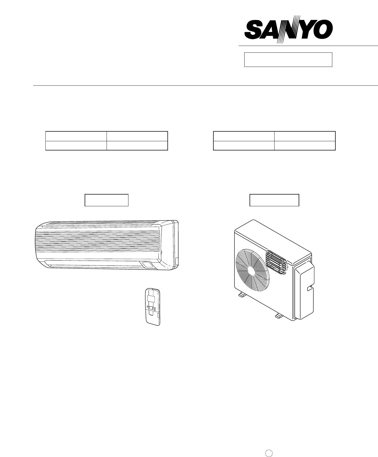
REFERENCE NO. SM700361WTECHNICAL & SERVICE MANUALKGS1411 / CG1411GAS HEATER AIR CONDITIONERFILE NO.Indoor Model No. Product Code No.KGS 1411 1 852
62-2-2. Outdoor Unit (2)Outdoor unit CG1411BurnerType Ribbon burnerQ’ty … Material, thickness inch (mm) 1 … Stainless steel, 0.0157 (0.4)NozzleQ’ty
For Parts or Service ContactSANYO FISHER SERVICE CORPORATIONA DIVISION OF SANYO LOGISTICS CORPORATION1411 West 190th Street, Suite 800, Gardena, CA 90
72-3. Other Component Specifications2-3-1. Indoor UnitIndoor unit KGS1411Transformer ATR-1581T2-URating Primary AC 115V, 60HzSecondary 13.7V, 0.5A
8Auto Reset Temperature LimitingModel CS-7LRating AC125V, 200mAThermal FuseModel X25Cut-off temp. 293°F (145°C)Transformer (TR) 4FF4L510034000Rating P
931-11/16 (805)10-5/8 (270)6-31/32 (177)3-29/32(99.5)2-5/16(58.5)1-5/8 (41.0)1-5/8 (41.0)Drain hose ø23/32 (18)Narrow tube ø1/4 (6.35)Wide tube ø3/8 (
1016-23/324-11/16(119) (425) (116)4-9/162-9/16(65)9-1/16 (230)25-31/32 (660)10-1/4 (260)5-21/32(144)2-17/32(64)3-5/16(84)2-5/32(55)2-21/32(67.5)9-1/1
113-2. Internal Components3-2-1. Indoor UnitIndoor unit KGS1411Air filterAir intake grilleAir cleaner filterOperation selectorPCB APCB BTransforme
123-2-2. Outdoor UnitOutdoor unit CG1411Printedcircuit board(solid state controller)TransformerCapacitorfor compressorPTCstarterOutdoorfan motorcap
133-3. Major ComponentsOutdoor unit CG1411(1) Combination Gas Valve (Proportional Control Valve)Type: Combination Gas ValveModel: UP13-27Material:
14(3) Main BurnerType: Ribbon BurnerMaterial: Stainless Steel, Thickness: 0.0157 inch (0.4 mm)(4) Combustion Blower6.457 (164)0.984 (25)0.433 (11)2.
15(5) Refrigerant Heater6.693 (170)10.827 (275)3.150 (80)AluminumCopper tubeOuter dia. 5/16Packing (both sides)Ceramic fiberSide wall (both sides)Alu
iIMPORTANT! Please Read Before StartingThis air conditioning system meets strict safety and operatingstandards. As the installer or service person, it
164. REFRIGERANT FLOW DIAGRAM4-1. Refrigerant Flow DiagramIndoor unit KGS1411 Outdoor unit CG1411( )( )Indoor unitWide tubeMufflerWide tub
175. PERFORMANCE DATA5-1. Performance ChartsIndoor unit KGS1411Outdoor unit CG1411● Cooling Characteristics ● Heating Characteristics115 VIndoor inl
185-2. Air Throw Distance ChartsIndoor unit KGS1411Room air temp.: 80°F (27°C)Fan speed: HighCoolingRoom air temp.: 70°F (20°C)Fan speed: HighHeating
195-3. Cooling CapacityIndoor unit KGS1411Outdoor unit CG1411115V single-phase 60HzTC : Total cooling capacity (BTU/h)SHC : Sensible heat capacit
205-4. Heating CapacityIndoor unit KGS1411Outdoor unit CG141120 30 404750 60Outdoor temperature °F (°C) D.B.0102030405060708090100110120Heating capa
216. ELECTRICAL DATA6-1. Electrical CharacteristicsIndoor unit KGS1411Outdoor unit CG1411Indoor Unit Outdoor Unit Complete UnitFan Motor Fan Motor C
226-2. Electric Wiring Diagrams(1) Indoor unit KGS1411WARNINGTo avoid electrical shock hazard, be sure todisconnect power before checking, servicing
23(2) Outdoor unit CG1411WARNINGTo avoid electrical shock hazard, be sure todisconnect power before checking, servicingand/or cleaning any electrical
24(3) Printed circuit board POW-CG1411K04C101K06K03K01CN08D11CN06 CN07 CN09D09CN04CN05F01Z01FUSE 250V/5AFLGNDJ37C09C01K07K02D10D14D16D12Q04TR1R60D13R
257. INSTALLATION INSTRUCTIONS7-1. Installation Site Selection7-1-1. Indoor UnitAVOID:● direct sunlight.● nearby heat sources that may affect perfo
iiTable of ContentsPage1. OPERATING RANGE ...
267-1-2. Outdoor UnitAVOID:● heat sources, exhaust fans, etc. (Fig. 4)● damp, humid or uneven locations.DO:● choose a place as cool as possible.● cho
27● provide a solid base (level concrete pad, concreteblock, 4 in. × 16 in. (10 × 40 cm) beams or equal),a minimum of 4 in. (10 cm) above ground level
287-3-1. Mounting on a Walla) Removable mounting1) Momentarily hold the remote control unit at the desiredmounting position. 2) Confirm that the air
298. FUNCTION8-1. Motion Explanation8-1-1. HeatingHeating operation begins with the refrigerant pump down cycle to move refrigerant into the heatin
308-1-3. Combustion Control(1) CombustionCombustion air is supplied into the burner for 20 seconds prior to ignition. The variable speed combustion
318-2. Cooling8-2-1. Room Temperature Control● Room temperature control is obtained by cycling the compressor ON and OFF under control of the roomte
328-2-2. Freeze Prevention (Cooling)● This function prevents freezing of the indoor heat exchange coil.● When the compressor has been running for 6 m
338-3. Heating8-3-1. Room Temperature Control● Room temperature control is obtained by cycling the compressor ON and OFF under control of the roomte
348-3-2. Refrigerant Control(1) Thermistor 11) Initial check:Must be able to confirm temperature increase of 2°F (1°C) within approximately 1 minute
358-3-3. Combustion Saving FunctionAfter Thermo. OFF occurs, shifts to Continuous Combustion Mode, Save Mode 1, or Save Mode 2, according tothe load
iii10. PROCEDURE FOR DISMANTLING THE UNIT10-1. Procedure for Dismantling the Indoor Unit ...
368-3-4. Cold Draft Prevention Function (During Heating Operation)This function prevents a cold draft from being released at the beginning of Heating
378-4. Fan Speed ControlDuring Cooling Operation Automatic fan speedTS + 4°F (2°C)3 minutes OFFTS + 2°F (1°C)Set Value (TS)HMLONOFFFan SpeedCompresso
388-5. Dry Operation (Dehumidification)● Dry operation uses the ability of the cooling cycle to remove moisture from the air, but by running at lowle
398-6. Automatic Operation(1) Normal● Set temperature can be shifted ± 4°F (2°C), in 2°F (1°C) steps.● If operation commences again within 2 hours
408-7. Freeze PreventionWhen the evaporation temperature drops to less than the temperatures stated below during Cooling or DryOperation, the operati
418-8. Overload Prevention (Heating)8-8-1. Indoor Unit● This function prevents overheating of the indoor heat exchange coil.● When the temperature o
9. OPERATION FLOWCHARTS9-1. Cooling, Dry 9-1-1. Starting FlowchartCool • DryOperation startsRoom temp. higherthan preset temp.Coil thermistor(higher t
Combustion lamp flashesWire misconnectionAmp. current is highAmp. current is lowInitialcheck 1 normalPower SupplyTroubleshootOperation startsOperation
4410. PROCEDURE FOR DISMANTLING THE UNIT10-1. Procedure for Dismantling the Indoor Unit(1) How to remove grille(2) How to remove PCBs➀ Close the f
45(3) How to remove electrical component box➀ Remove the screw for ground screw (green, 1).(4) How to remove drain panRemove the screw (1) attaching
11. OPERATING RANGETemperature Indoor Air Intake Temp. Outdoor Air Intake Temp.Cooling Maximum 95°F (35°C) D.B. 115°F (46.1°C) D.B.71°F (21.7°C) W.B.
46(5) How to detach heat exchanger➀ Remove the screws (2) attaching the metal clipof the tube. Extend the supplementary tubing atthe back of the unit
4710-2. Procedure for Dismantling the Outdoor Unit(1) How to remove the external panels(2) How to detach the rear panel➀ Remove the screws (2) of t
48(4) How to detach combination valve and gas conduit➀ Remove the screw (1) for the attachment plate of the combination valve in back of the main uni
49(6) How to detach ignition probe and flame sensor electrode➀ Detach the connector of the ignition probe.➁ Remove connector CN17 from outdoor unit P
5011. POINTS TO DIAGNOSE11-1. Indoor Unit Alarm Signal11-2. Manifold Pressure● To set manifold pressure there are 2 settings – low pressure and hig
5111-3. Checking Electrical Components11-3-1. ComponentsFlow Measurement Target (Normal) Upper: Volt, Amp.RemarksNo. CO. No. Wire Color (Normal) Low
5211-3-2. Indoor UnitIndoor UnitTransformer Voltage • Coil ResistanceMeasurement Target (Normal) Upper: VoltageCN Wire Color (Normal) Lower: Resistan
5312. TROUBLESHOOTING12-1. Check Before and After Troubleshooting12-1-1. Check Power Supply Wiring● Check that power supply wires are correctly con
5412-2. When the Air Conditioner Does Not Work at All (Both Indoor andOutdoor Units) — Operation Lamp Does Not Light12-2-1. Malfunction in Power Supp
55No. Caused by (outdoor unit)LED lampsMeaning2 3 4 5— Normal ●● ●● ●● ●● Normal operation— Defective in IC chip (E2PROM) ●● ●● ●● ● Canno
2DATA SUBJECT TO CHANGE WITHOUT NOTICE.Remarks: Rating conditions areCooling: Indoor air temperature 80°F D.B. / 67°F W.B.Outdoor air temperature 95°F
5612-3-5. Indoor Fan is Defective➀ Check if the indoor fan is locked up.Turn fan gently by hand.➁ Check if motor circuit is defective.Set temperature
5712-3-7. Outdoor Unit Power Supply FailureMeasure voltage between Terminals 5 – 6 on terminal block of outdoor unit.Set temperature by remote contro
5812-3-10. Outdoor Unit Compressor Motor Defective➀ Check if compressor motor is locked up.Set temperature by remote controller so air conditioner op
5912-5. Flap Motor Does Not Work12-5-1. Louver Motor Defective➀ Set to cooling operation with flap to oscillate (movie) using remote controller and m
6012-6-3. Safety Device OperatedFailure Display on Outdoor Unit PCB: ●● ● ●● ●Check safety device.➀ Disconnect safety device connector (CN12, 2P, WH
61Normal ORG – ORG DC 90 – 120 VNormal WHT – WHT 1 – 2.5 kΩNormal ORG – ORG 1 – 2.5 kΩIn case of abnormality ➞ Replace heating electromagnetic valv
6212-6-7. Combustion Blower Motor Abnormal RevolutionFailure Display on Outdoor Unit PCB: ● ●● ●● ●Check combustion blower motor.➀ Measure AC voltag
6312-7. Reset Method When Error Occurs During Heating OperationWait for 4 minutes or more after the power is on, and then press the operation button o
12-8. Failure Display on Outdoor Unit and Correction MethodNo. Caused by (outdoor unit) LED lampsMeaningError Detected Points to Diagnose Correction M
6513. SPECIAL PRECAUTIONS WHEN SERVICING THE UNITImportant! For your personal safety, be sure to read and understand the following precautions before
3Dimensions & Weight Indoor Unit Outdoor UnitUnit dimensions Height inch (mm) 10-5/8 (270) 23-7/32 (590)Width inch (mm) 31-11/16 (805) 28-1/2 (724
13-2. Refrigerant Recovery13-2-1. Open service valve to recover refrigerant into refrigerantrecovery unit.13-3. Service on Outdoor Unit13-3-1. After
6713-4-2. Connect the vacuum pump and a manifold valve as shown Fig. 1. Confirm that all connections are cor-rectly made.In order to withstand negativ
6813-5-5. If it is not possible to completely charge the unit with the proper amount of refrigerant, you can do anadditional charging after installing
1INSTRUCTION MANUALKGS 1411 + CG1411APPENDIX
For Your Safety Read Before OperationWARNING:If you do not follow these instructions exactly, a fire orexplosion may result causing property damage,pe
ContentsPageFor Your Safety Read Before Operation ... 2Product Information ...
FeaturesThis air conditioner is equipped with cooling, drying and heating functions. This air conditioner is arefrigerant heating type unit which uses
Installation Location•We recommend that this air conditioner be installed properly byqualified installation technicians in accordance with the Install
Safety Instructions•Read this Instruction Manual carefully before using this air conditioner.If you still have any difficulties or problems, consult y
Names of PartsNOTEThis illustration is based on the external appearance of a standard model.Consequently, the shape may differ from that of the air co
42-2. Major Component Specifications2-2-1. Indoor UnitIndoor unit KGS1411DATA SUBJECT TO CHANGE WITHOUT NOTICE.Control PCBPart No. POW-KGS14A, BCo
Unit Display and Operation SelectorREMOTE CONTROLreceiverThis section picks up infrared signals from the remote control unit(transmitter).Operation se
Remote Control Unit (Display)SET TEMP.NORMALONOFF1HR.H(1) Operation modeAUTO...HEAT...
Remote Control UnitNOTEThe illustration above pictures the remote control unit after the cover hasbeen lowered and removed.Transmitter When you press
Remote Control Unit (continued)MODE selector buttonGreen or red (AUTO)Red (HEAT)Orange (DRY)Green (COOL)Green (FAN)Use this button to select the AUTO,
Using the Remote Control UnitHow to Install BatteriesNOTE•The batteries last about six months, depending on how much you usethe remote control unit. R
Using the Remote Control Unit (continued)Mounting the RemoteControl UnitMounting on a wall A. Removable mounting1) Momentarily hold the remote control
Operation with the RemoteControl Unit1. Automatic OperationNOTECheck that the circuit breaker on the power panel is turned on and that theoperation se
Operation with the Remote Control Unit (continued)Press TEMP. to change the temperature setting.•The type of operation and the temperature setting wil
Operation with the Remote Control Unit (continued)2. Manual OperationNOTECheck that the circuit breaker on the power panel is turned on and that theop
Operation with the Remote Control Unit (continued)NOTE•Choose the best position in the room for the remote control unit, whichalso acts as the sensor
5DATA SUBJECT TO CHANGE WITHOUT NOTICE.2-2-2. Outdoor Unit (1)Outdoor unit CG1411Control PCBPart No. CG1411Controls MicroprocessorControl circuit f
Operation with the Remote Control Unit (continued)4. Fan OnlyIf you want to circulate air without any temperature control, follow thesesteps:STEP 1: P
Operation with the Remote Control Unit (continued)A. In Cooling and DRYMode:(and )B. In Heating Mode:()When the night setback mode is selected, the ai
Special Remarks‘‘DRY’’ ( ) OperationHow it works?•Once the room temperature reaches the level that was set, the unitrepeats the cycle of turning on an
Using the 12-Hour ON and OFFTimer1. TIMER ON mode(Example)After the length of time set for TIMER ON elapses, the unit beginsoperating.ONHThe display d
Using the 1-Hour OFF Timer1. 1-Hour OFF Timer This function causes the unit to operate for one hour and then stop,regardless of whether the unit is on
Adjusting the Airflow Direction1. Horizontal The horizontal airflow can be adjusted by moving the vertical vanes withyour hands to the left or right.C
Operation without the RemoteControl UnitIf you have lost the remote control unit or it has trouble, follow the stepsbelow.1. When the air conditioner
Care and Cleaning (continued)Anti-mold filter The anti-mold filter behind the air intake grille should be checked andcleaned at least once every two w
Care and Cleaning (continued)Air cleaning filter(not provided)The air cleaning filter removes dust and dirt from the air, and reduces odorsand smoke f
TroubleshootingIf your air conditioner does not work properly, first check the following points before requesting service. If itstill does not work pr
Related products and manuals for Heat pumps Sanyo CG1411
 (202 pages)
(17 pages)
(202 pages)
(17 pages)
© 2020, manymanuals.com. All rights reserved. | 1.947 s |
 Manymanuals.com
 Manymanuals.de
 Manymanuals.fr
 Manymanuals.it
 Manymanuals.pl
 Manymanuals.cz
 Manymanuals.es
 Manymanuals-pt.com
Comments to this Manuals