Sanyo MPR-1411R User Manual
Browse online or download User Manual for Refrigerators Sanyo MPR-1411R. Sanyo MPR-1411R User Manual
- Page / 41
- Table of contents
- BOOKMARKS
Rated. / 5. Based on customer reviews
- 38 -- 38 -
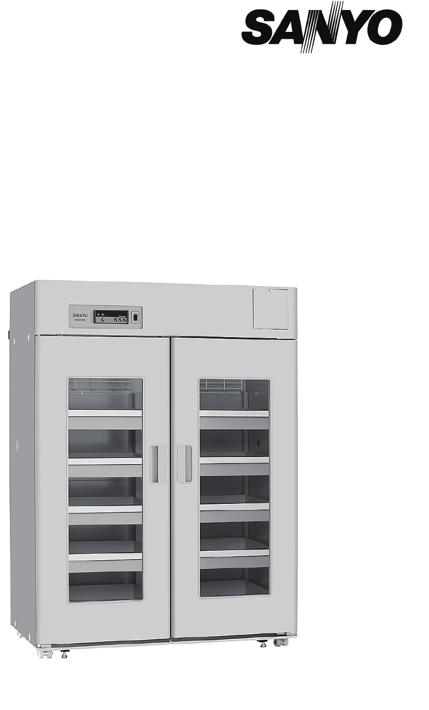
MPR-1411
MPR-1411R
Pharmaceutical Refrigerator
INSTRUCTION MANUAL
MPR-1411R
- MPR-1411 1
- MPR-1411R 1
- CONTENTS 2
- INTRODUCTION 3
- - 41 -- 41 4
- - 42 -- 42 5
- - 43 -- 43 6
- - 44 -- 44 7
- ENVIRONMENTAL CONDITIONS 8
- REFRIGERATOR COMPONENTS 10
- INSTALLATION SITE 13
- INSTALLATION 14
- START-UP OF UNIT 15
- STOCK OF CONTAINERS 16
- ALARM TEMPERATURE SETTING 18
- KEY LOCK FUNCTION 21
- DEFROST CYCLES 22
- REMOTE ALARM TERMINAL 22
- ROUTINE MAINTENANCE 24
- TROUBLE SHOOTING 27
- DISPOSAL OF UNIT 28
- OPTIONAL COMPONENTS 33
- OPTIONAL COMPONENTS 38
- SPECIFICATIONS 39
- PERFORMANCE 39
- Safety check sheet 40
- SANYO Electric Co., Ltd 41
- Printed in Japan 41
Summary of Contents
Page 1 - MPR-1411R
- 38 -- 38 -MPR-1411MPR-1411RPharmaceutical RefrigeratorINSTRUCTION MANUALMPR-1411R
Page 2 - CONTENTS
- 47 -9 REFRIGERATOR COMPONENTS 1. Front cover: A front cover opens when a bottom part is pulled to the front. Open this cover when you use cle
Page 3 - INTRODUCTION
- 48 -10 REFRIGERATOR COMPONENTS Control panel1. Door check indicator (DOOR): The red LED lamp is lit when the outer door is opened.2. Alarm lamp (A
Page 4 - - 41 -- 41
- 49 -11 REFRIGERATOR COMPONENTS Inside of front cover1. Condenser filter: This filter is for prevention of condenser clogged up. Clean the filter
Page 5 - - 42 -- 42
- 50 -12 INSTALLATION SITE To operate this unit properly and to obtain maximum performance, install the unit in a location with the following condit
Page 6 - - 43 -- 43
- 51 -13 INSTALLATION 1. Removing the packaging materials and tapes Remove all transportation packaging materials and tapes. Open the doors and v
Page 7 - - 44 -- 44
- 52 -14 START-UP OF UNITFollow the procedures for the initial and consequent operations of the unit.1. Connect the power cord to the dedicated ou
Page 8 - ENVIRONMENTAL CONDITIONS
- 53 -15 STOCK OF CONTAINERSAlways distribute items so as not to disturb the air circulation in the chamber. Disruption of the air flow can cause
Page 9
- 54 -16 CHAMBER TEMPERATURE SETTING Table 1 shows the basic procedure for setting the chamber temperature. Perform key operations in the sequenc
Page 10 - REFRIGERATOR COMPONENTS
- 55 -17 ALARM TEMPERATURE SETTING This unit is provided with both high and low temperature alarms. The temperature at which the alarm is activated
Page 11
- 56 -18 SETTING OF DELAY OF DOOR ALARM The door check indicator is light when the door is opened, and the alarm buzzer sounds with some delay to
Page 12
- 39 -- 39 -1CONTENTSINTRODUCTION P. 2 PRECAUTIONS FOR SAFE OPERATION P. 3 ENVIRONMENTAL CONDITIONS P. 7 REFRIGERATOR COMPONENTS P.
Page 13 - INSTALLATION SITE
- 57 -19 SETTING OF ALARM RESUME TIME The alarm buzzer and remote alarm are silenced by pressing he alarm buzzer stop key (BUZZER) on the control
Page 14 - INSTALLATION
- 58 -20 KEY LOCK FUNCTION This unit is provided with a key lock function. When the key lock is ON, change of temperature setting through the key
Page 15 - START-UP OF UNIT
- 59 -21 DEFROST CYCLES 㩵 Cycle defrost When the ambient humidity is high, or a large amount of damp product is being stored inside the chamber, the
Page 16 - STOCK OF CONTAINERS
- 60 -22 ALARMS & SAFETY FUNCTIONS This unit has the alarms and safety functions shown in Table 7, and also self diagnostic functions. Table 7
Page 17
- 61 -23 ROUTINE MAINTENANCE WARNINGAlways disconnect the power supply to the unit prior to any repair or maintenance of the unit in order to preven
Page 18 - ALARM TEMPERATURE SETTING
- 62 -24 ROUTINE MAINTENANCE Replacement of fluorescent lampThe fluorescent lamp is placed vertically at the center of the chamber. Follow the proc
Page 19
- 63 -25 ROUTINE MAINTENANCE Replacement of glow starterA glow starter is located inside the front cover. 1. Disconnect the power supply plug. 2. Re
Page 20
- 64 -26TROUBLE SHOOTINGIf the unit malfunctions, check out the following before calling for service. Malfunction Check/Remedy If nothing operate
Page 21 - KEY LOCK FUNCTION
- 65 -27 DISPOSAL OF UNIT WARNINGIf the unit is to be stored unused in an unsupervised area for an extended period ensure that children do not have
Page 22 - REMOTE ALARM TERMINAL
- 66 -28 DISPOSAL OF UNIT (English)FOR EU USERS The symbol mark and recycling systems described below apply to EU countries and do not apply to coun
Page 23
- 40 -- 40 -2 INTRODUCTIONŶ Read this manual carefully before using the appliance and follow the instructions for safety operation. Ŷ Sanyo never gua
Page 24 - ROUTINE MAINTENANCE
- 67 -29 DISPOSAL OF UNIT (French) POUR LES UTILISATEURS DE UE Le symbole et les systèmes de recyclage évoqués ci-dessous s'appliquent uniqueme
Page 25
- 68 -30 DISPOSAL OF UNIT (Portuguese) PARA UTILIZADORES DA UE O símbolo e os sistemas de reciclagem descritos abaixo aplicam-se aos países da UE e
Page 26
- 69 -31 DISPOSAL OF UNIT (Dutch) VOOR GEBRUIKERS IN DE EU Het symbool en de recycleersystemen die hieronder beschreven worden, zijn van toepassing
Page 27 - TROUBLE SHOOTING
- 70 -32 OPTIONAL COMPONENTSAutomatic temperature recorderAn automatic temperature recorder is available for this refrigerator as an optional access
Page 28 - DISPOSAL OF UNIT
- 71 -33 OPTIONAL COMPONENTS6. An attached binder (two pcs) is used for the fan cover of the top of the chamber as the Fig. 5, and a temperature sen
Page 29
- 72 -34 OPTIONAL COMPONENTS3. Remove the black rubber caps (inside and outside) on the access port located at the top corner of the unit and take t
Page 30
- 73 -35 OPTIONAL COMPONENTSAttachment of battery kit MPR-48BThe alarm lamp blinks and the alarm buzzer sounds to notice the power failure when a ba
Page 31
- 74 -36 OPTIONAL COMPONENTS5. Put the battery fixture over the battery and fix the battery box and battery fixture by four screws. (Fig. 4) 6. E
Page 32
- 75 -37OPTIONAL COMPONENTSSetting for battery before startingAlways perform the setting shown below after the installation of battery for power failu
Page 33 - OPTIONAL COMPONENTS
- 76 -38 SPECIFICATIONSName Pharmaceutical RefrigeratorModel MPR-1411 MPR-1411R External dimensions W1440 x D830 x H1950 (mm) Internal dimensi
Page 34
- 41 -- 41 -3 PRECAUTIONS FOR SAFE OPERATIONIt is imperative that the user complies with this manual as it contains important safety advice.Items and
Page 35
- 77 -39CAUTIONPlease fill in this form before servicing. Hand over this form to the service engineer to keep for his and your safety.Safety check s
Page 36
SANYO Electric Co., LtdPrinted in Japan
Page 37
- 42 -- 42 -4 PRECAUTIONS FOR SAFE OPERATION Do not use the unit outdoors. Current leakage or electric shock may result if the unit is exposed to
Page 38 - OPTIONAL COMPONENTS
- 43 -- 43 -5 PRECAUTIONS FOR SAFE OPERATION Ensure you do not inhale or consume medication or aerosols from around the unit at the time of maintenan
Page 39 - PERFORMANCE
- 44 -- 44 -6 PRECAUTIONS FOR SAFE OPERATION Use a dedicated power source (a dedicated circuit with a breaker) as indicated on the rating label attac
Page 40 - Safety check sheet
- 45 -- 45 -7 ENVIRONMENTAL CONDITIONS This equipment is designed to be safe at least under the following conditions (based on the IEC 61010-1): 1.
Page 41 - Printed in Japan
- 46 -8 REFRIGERATOR COMPONENTS 13415783921211 10MPR-1411RMPR-141114156Rear side17181216
© 2020, manymanuals.com. All rights reserved. | 2.759 s |
 Manymanuals.com
 Manymanuals.de
 Manymanuals.fr
 Manymanuals.it
 Manymanuals.pl
 Manymanuals.cz
 Manymanuals.es
 Manymanuals-pt.com
Comments to this Manuals