Sanyo C2462R User Manual
Browse online or download User Manual for Toy parts Sanyo C2462R. Sanyo C2462R User's Manual
- Page / 58
- Table of contents
- BOOKMARKS
- TECHNICAL DATA 1
- SERVICE MANUAL 1
- Important 2
- Table of Contents 3
- 1. OPERATING RANGE 4
- 2. SPECIFICATIONS 10
- 3. DIMENSIONAL DATA 13
- 4. COOLING CAPACITY 15
- 5. PERFORMANCE CHARTS 17
- 6. AIR THROW DISTANCE CHART 21
- 7. REFRIGERANT FLOW DIAGRAM 22
- 8. INSTALLATION INSTRUCTIONS 23
- 9. ELECTRICAL DATA 29
- • Electric Wiring Diagram 30
- • Schematic Diagram 32
- 11. PROCESSES AND FUNCTIONS 35
- 2217_X_S 38
- 12. SERVICE PROCEDURES 39
- • Check coil resistance of 45
- compressor motor magnetic 45
- 1035_X_S 45
- 0633_X_S 47
- 1039_X_S 48
- 0639_X_S 51
- 0640_X_S 51
- 0641_X_S 51
- 1041_X_S 53
- 1043_X_S 54
- 1042_X_S 54
- SM830092 58
Summary of Contents
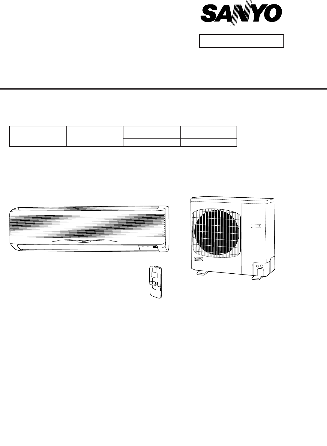
– 1 –SM830092854648419200KS2462R C2462RCL2462RIndoor Unit Outdoor UnitSPLIT SYSTEM AIR CONDITIONERTECHNICAL DATA&SERVICE MANUALFILE NO. INDOOR MO
– 10 –SM8300922. SPECIFICATIONS(3) Other Component Specifications(A) Indoor UnitMODEL No. KS2462RPower Transformer ATR – T5Rated Primary AC 230 V, 60
– 11 –SM8300922. SPECIFICATIONS(3) Other Component Specifications(A) Outdoor UnitMODEL No. C2462RCompressor Motor Magnetic Contactor FC - 1SULCoil rat
– 12 –SM8300922. SPECIFICATIONS(3) Other Component Specifications(B) Outdoor UnitMODEL No. CL2462RCompressor Motor Magnetic Contactor FC - 1SULCoil ra
– 13 –SM8300923. DIMENSIONAL DATA(1) Indoor Unit: KS2462R6-27/32Center of tubing hole (2 places)Narrow tube 3/8"(ø9.52)Wide tube 3/4"(ø19.0
– 14 –SM8300923. DIMENSIONAL DATA(2) Outdoor Unit: C2462R, CL2462R13-3/836-5/86-23/3225-31/32374-3/814-31/3216-7/818-1/1625/323/415-15/16Dimension : i
– 15 –SM8300924. COOLING CAPACITYTC : Total Cooling Capacity (BTU / h)SHC : Sensible Heat Capacity (BTU / h)CI : Compressor Input (kW)Rating condition
– 16 –SM8300924. COOLING CAPACITYTC : Total Cooling Capacity (BTU / h)SHC : Sensible Heat Capacity (BTU / h)CI : Compressor Input (kW)Rating condition
– 17 –SM8300925. PERFORMANCE CHARTS(1) Operating Current1Indoor Unit: KS2462R Outdoor Unit: C2462ROperating current characteristics versus outdoor amb
– 18 –SM8300925. PERFORMANCE CHARTS(1) Operating Current2Indoor Unit: KS2462R Outdoor Unit: CL2462ROperating current characteristics versus outdoor am
– 19 –SM8300925. PERFORMANCE CHARTS230V / 208 V• Low PressureLow pressure characteristics versus outdoor ambient temperature and indoor temperature.(I
– 2 –SM830092ImportantCAUTIONWhen Installing………………………………………………………………………In a RoomProperly insulate any tubing run inside a room to prevent“sweating” th
– 20 –SM8300925. PERFORMANCE CHARTS230 / 208V(2) High and Low Pressure2Indoor Unit: KS2462R Outdoor Unit: CL2462R• High PressureHigh pressure characte
– 21 –SM8300926. AIR THROW DISTANCE CHARTHorizontal distance (ft.)Axis air velocity (ft./sec.)Vertical distance (ft.)Room air temp. : 80°F (26.7°C)Fan
– 22 –SM8300927. REFRIGERANT FLOW DIAGRAMIndoor Unit: KS2462R Outdoor Unit: CL2462RIndoor Unit: KS2462R Outdoor Unit: C2462RCondenserCompressorAccumul
– 23 –SM8300928. INSTALLATION INSTRUCTIONSTable 3Max. Allowable Tubing Limit of Tubing Limit of Elevation Required Amount of Model Length at Shipment
– 24 –SM8300928. INSTALLATION INSTRUCTIONSMinimum height from floor level 5 ft.Indoor UnitWallFloor level2205_M_S2) Selecting the Installation
– 25 –SM8300928. INSTALLATION INSTRUCTIONSOutdoor UnitAVOID:heat sources, exhaust fans, etc. Fig. 4damp, humid or uneven locations.DO:choose a place a
– 26 –SM8300928. INSTALLATION INSTRUCTIONSWind Shield for "CL" ModelIt is recommended to use wind shields for "CL" model(Fig. 5b).
– 27 –SM8300928. INSTALLATION INSTRUCTIONS3) Electrical WiringGeneral Precautions on Wiring(1) Before wiring, confirm the rated voltage ofthe unit as
– 28 –SM8300928. INSTALLATION INSTRUCTIONS7-2. Recommended Wire Length and Wire Diameter for Power Supply System7-3. Wiring System DiagramModelsTime D
– 29 –SM8300929. ELECTRICAL DATAIndoor Unit Outdoor UnitComplete UnitFan Motor Fan Motor CompressorPerformance at 230 - 208 V / 1 phase / 60 HzRating
– 3 –SM830092Table of Contents1. OPERATING RANGE ... 42. SPECIFICA
– 30 –SM83009210. ELECTRICAL WIRING DIAGRAMS(1) Indoor Unit1KS2462R876543218765432112345123451234512345FLPCONNECTORFLAP25P [BLK]FLAP15P [WHT]LAMP 4P
– 31 –SM83009210. ELECTRICAL WIRING DIAGRAMSCMRC12P (GRN)8P (WHT)2P (WHT)63PL31321314TWSVRUABPSEARTHTERMINALCRSGRN/YEL52C5781312126242Y49FOEARTHTERMIN
– 32 –SM83009210. ELECTRICAL WIRING DIAGRAMS2Y52C122YTERMINALPLATE (6P)2YRC263PHCLHCRSRC152C– 1– 21Y1YHMFMOCM651249FO52C23S• Schematic DiagramSymbols
– 33 –SM83009210. ELECTRICAL WIRING DIAGRAMS• Electric Wiring Diagram124GL1L2RC2FMORC1PNKBRNGRYGRYWHTVLTYELPNKBRNGRYBLKWHTVLTYEL212143436565878P8P (WH
– 34 –SM83009210. ELECTRICAL WIRING DIAGRAMS• Schematic Diagram312121TRAC 208V230VAC 14VTHOUTDOORTEMPERATURE1RY175 965 7FMORC2COMCOMRC1RY3-1RY1RY2HLM3
– 35 –SM83009211. PROCESSES AND FUNCTIONS(1) Room Temperature ControlThe Unit adjusts room temperature by turning the outdoor unit’s compressor ON and
– 36 –SM83009211. PROCESSES AND FUNCTIONS(2) Dry Operation (Dehumidification)Dry operation uses the ability of the cooling cycle to remove moisture fr
– 37 –SM830092(3) Freeze PreventionFreeze Prevention keeps the indoor heat exchange coil from freezing. Freezing reduces theefficiency of the unit, an
– 38 –SM830092(4) Outdoor Fan Speed Control(1) C2462R Type• In low outdoor temperature, the outdoor fan is set automatically from HIGH to LOWto preven
– 39 –SM830092(1) Troubleshooting1) Check before and after TroubleshootingMany problems may happen because of wiring or power supply problems, so yous
– 4 –SM8300921. OPERATING RANGEKS2462R / C2462RKS2462R / CL2462RTemperature Indoor Air Intake Temp. Outdoor Air Intake Temp.Maximum 95 °F DB / 71 °F W
– 40 –SM8300922) Air Conditioner does not Operate1Circuit breaker trips (or fuse blows).(a) When the circuit breaker is set to ON, it is tripped soon.
– 41 –SM83009212. SERVICE PROCEDURES(b) Circuit breaker trips in several minutes after turning the air conditioner on.• There is a possibility of shor
– 42 –SM83009212. SERVICE PROCEDURESC. Check “Operation selector” switch in the indoor unit.D. Check compressor motor protectors.(a) High pressure swi
– 43 –SM83009212. SERVICE PROCEDURESF. Check. auxiliary relay. (1Y or 2Y)0620_X_S• Check coil resistance of auxiliary relay.
– 44 –SM83009212. SERVICE PROCEDURES3) Outdoor Unit does not Run.A. Check COOL / FAN selector switch in the remote control unit.B. Check set temperatu
– 45 –SM83009212. SERVICE PROCEDURESC. Check compressor motor magnetic contactor.D. Check indoor unit P.C.B.0628_X_S• Check voltage between terminals
– 46 –SM83009212. SERVICE PROCEDURES5) Some Part does not Operate.A. Indoor fan does not run.4) Indoor Unit does not Run.(Indoor fan and flap motor do
– 47 –SM83009212. SERVICE PROCEDURES7) Outdoor Fan Speed is not Switched from High to Low even when the OutdoorTemperature Falls below 78 °F. (C2462R
– 48 –SM83009212. SERVICE PROCEDURES9) Outdoor Fan does not Run for CL2462R.10) Compressor does not Run.• Check fuse on PCB Ass’y in outdoor unit fo
– 49 –SM83009212. SERVICE PROCEDURES11) Poor Cooling.12) Excessive Cooling.• The set temperature is too low.• Is the remote control unit installed a
– 5 –SM8300922. SPECIFICATIONSMODEL No. Indoor UnitKS2462ROutdoor Unit C2462RPOWER SOURCE 230 - 208 V / 1 Phase / 60 HzPERFORMANCE CoolingCapacitykW7
– 50 –SM83009212. SERVICE PROCEDURES(2) A Sensor is Defective.1Indoor (heat exchanger) coil temp. Sensor is defective.(a) Open (=No continuity in sens
– 51 –SM83009212. SERVICE PROCEDURES(3) Checking the Electrical Components1) Measurement of InsulationResistance•The electrical insulation is acceptab
– 52 –SM83009212. SERVICE PROCEDURES2) Checking the Protective Devices• Disconnect the connector, which consists of P (plug) and S (socket) when you w
– 53 –SM830092Fan motorcapacitorCompressor motorcapacitor1041_X_SMultimeterΩFig. 213) Checking the Electrical Parts1Power transformer ...
– 54 –SM83009212. SERVICE PROCEDURES6Continuity of fuse on P.C.B.Ass’y• Check for continuity using a multim-eter as shown in Fig. 22.Method Used to Re
– 55 –SM83009212. SERVICE PROCEDURES11. REFRIGERANT R410A: SPECIAL PRECAUTIONS WHEN INSTALLING UNIT11-1. Characteristics of New Refrigerant R410A11-
– 56 –SM83009212. SERVICE PROCEDURESTubing precautionsRefrigerant R410A is more easily affected by dust or moisture compared to R22, thus be sure to t
– 57 –SM83009212. SERVICE PROCEDURES11-3. Tools Specifically for R410AFor servicing, use the following tools for R410ATo prevent other refrigerants (
– 58 –SM830092
– 6 –SM8300922. SPECIFICATIONSMODEL No. Indoor UnitKS2462ROutdoor Unit CL2462RPOWER SOURCE 230 - 208 V / 1 Phase / 60 HzPERFORMANCE CoolingCapacitykW
– 7 –SM8300922. SPECIFICATIONS(2) Major Component Specifications(A) Indoor UnitMODEL No. KS2462RSource 230 - 208 V / 1 phase / 60 HzRemote controller
– 8 –SM8300922. SPECIFICATIONS(2) Major Component Specifications(B) Outdoor Unit+ 0– 0.15DATA SUBJECT TO CHANGE WITHOUT NOTICEMODEL No. C2462RSource 2
– 9 –SM8300922. SPECIFICATIONS(2) Major Component Specifications(B) Outdoor UnitMODEL No. CL2462RSource 230 - 208 V / 1 phase / 60 HzController P.C.B.
Related products and manuals for Toy parts Sanyo C2462R
 (21 pages)
© 2020, manymanuals.com. All rights reserved. | 0.356 s |
 Manymanuals.com
 Manymanuals.de
 Manymanuals.fr
 Manymanuals.it
 Manymanuals.pl
 Manymanuals.cz
 Manymanuals.es
 Manymanuals-pt.com
Comments to this Manuals