Sanyo Carbon Monoxide Alarm UV User Manual
Browse online or download User Manual for Power generators Sanyo Carbon Monoxide Alarm UV. Sanyo Carbon Monoxide Alarm UV User's Manual
- Page / 68
- Table of contents
- TROUBLESHOOTING
- BOOKMARKS
- MCO-19AIC㩿UV㪀 1
- MCO-19AIC 1
- CONTENTS 2
- INTRODUCTION 3
- LABELS ON THE INCUBATOR 8
- EMVIRONMENTAL CONDITIONS 8
- For MCO-19AIC(UV) or 9
- Control panel and keypad 11
- Remote alarm terminals 12
- INSTALLATION SITE 13
- INSTALLATION 14
- Connecting a CO 15
- gas cylinder 15
- PREVENTING CONTAMINATION 16
- PRECAUTIONS FOR CULTURES 17
- Using the Unlock Key 18
- WARNING 18
- LCD PANEL㩷 19
- BASIC PARAMETERS 21
- 㩷㩷Setting the key lock㩷 22
- 㩷㩷Removing the key lock㩷 22
- ALARM PARAMETERS㩷 26
- 㩷㩷Using the UV lamp㩷 27
- OTHER PARAMETERS㩷 31
- DISPLAYING THE LOG㩷 34
- Transferring data 35
- WATER LEVEL SENSOR 36
- ROUTINE MAINTENANCE 37
- CAUTION 40
- DECONTAMINATION 41
- decontamination 43
- decontamination reagent 46
- CALIBRATION 49
- TROUBLESHOOTING 51
- DISPOSING OF THE CO 53
- INCUBATOR 53
- (Italian) 56
- AUTOMATIC CO 58
- CYLINDER CHANGEOVER 58
- AUTOMATIC CO 60
- DENSITY CALIBRATION 60
- STACKING INCUBATORS 63
- SPECIFICATIONS 65
- PERFORMANCE 66
- Safety check sheet 67
- Printed in Japan 68
Summary of Contents
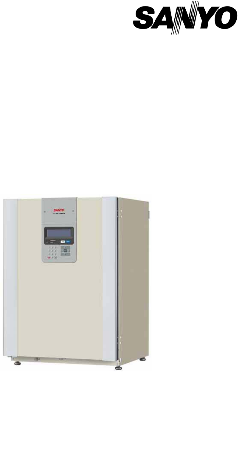
91MCO-19AIC㩿UV㪀MCO-19AIC CO2 Incubator INSTRUCTION MANUAL
1009 1. Outer door: The outer door is held to the frame with a magnetic seal. A door heater is installed in the door panel. The door opening is re
10110 Control panel and keypad 1. LCD panel 2. Upper limit regulator: This regulator is used to set the upper temperature
10211 Remote alarm terminals The remote alarm terminals are located at the rear right side. The remote alarm terminals are a c
10312 INSTALLATION SITE For correct operation of the Incubator, install it in a location with the following conditions. WARNING When using CO2 gas f
10413 Leveling feet INSTALLATION 1. Remove the packing tape and clean up. Remove all the tape that is securing the doors and inner attachments. O
10514 Connecting a CO2 gas cylinder WARNING When connecting a gas cylinder to the Incubator, confirm the gas type. Confirm that the connections
10615 PREVENTING CONTAMINATION To prevent contamination of the chamber, select a suitable installation site. z Avoid locations with high temperatu
10716 PRECAUTIONS FOR CULTURES z Leave space between culture containers. Always leave space for ventilation between culture containers (Petri dishe
10817 Using the Unlock Key z Unlocking when power is interrupted If power is interrupted to the MCO-19AIC(UV)/19AIC with an MCO-HL installed,
10918LCD PANEL㩷㩷The following display (called the Top Display) will appear when the power switch is turned ON. The default temperature is 37.0oC and t
921 CONTENTS INTRODUCTION 2 PRECAUTIONS FOR SAFE OPERATION 3 LABELS ON THE INCUBATORS 7 ENVIRONMENTAL CONDITIONS 7 INCUBATOR COM
11019BASIC OPERATIONS ON CONTROL PANEL㩷㩷The following operation are possible through control panel:㩷㩷1. Setting the temperature䊶䊶䊶The chamber temperat
11120BASIC PARAMETERS 㩷㩷 Setting the chamber temperature and CO2 density㩷㩷The setting procedure for the chamber temperature and CO2 density are given
11221㩷㩷㩷㩷Setting the key lock㩷㩷1. To set the key lock, change the value of the key lock parameter from 0 to 1 on the Stand-by Setting Display and pres
11322㩷㩷Note: The buzzer will sound for a long time if the wrong password is entered. Enter the correct password. The password for releasing the key l
11423㩷㩷4. Enter the new user password (4 digits), select OK, and press the ENTER Key. 㩷㩷㩷㩷㩷㩷㩷㩷㩷㩷㩷㩷5. Enter the new user password again, select OK, and
11524㩷㩷 Setting the upper limit alarm temperature 㩷An upper limit temperature alarm is provided with the Incubator. The alarm temperature can be ch
11625ALARM PARAMETERS㩷㩷1. Press the MENU Key from the Top Display to display the menu, select Tools, and press the ENTER Key. 㩷㩷㩷㩷㩷㩷㩷㩷㩷㩷㩷2. Select Ala
11726UV LAMP PARAMETERS 㩷A UV lamp is used with the MCO-19AIC(UV) or the MCO-19AIC with an MCO-19UVS UV Lamp Expansion Kit installed. Use the followin
11827 㩷㩷㩷Precautions when using the UV lamp 㩷WARNING Do not look directly at UV light. UV light is harmful to the eyes. z Always use the humidifying
11928 㩷 Setting the UV lamp ON period 㩷Use the following procedure to change the setting of the UV lamp ON period.㩷㩷1. Press the MENU Key from the
932 INTRODUCTION Ŷ Read this manual carefully before using the Product and follow the instructions for safety operation. Ŷ Sanyo disavows any respo
12029 㩷x The UV timer can be set from 0 to 30 min. The default setting is for 5 min. When the UV timer is set to zero, the UV lamp will not light. x I
12130OTHER PARAMETERS㩷㩷 Setting the date, time, and log interval 㩷1. Press the MENU Key from the Top Display to display the menu, select Tools and
12231㩷㩷3. The Date Time Display will appear. Set the date, time and log interval. 㩷㩷㩷㩷㩷㩷㩷㩷㩷㩷㩷䊶Entering the date Example for March 1, 2009: Enter 090
12332㩷㩷㩷㩷Initial settings (LCD/DAQ parameters) 㩷1. Select LCD/DAQ Setting from the Select Tools Display, press the MENU Key to display the menu, selec
12433DISPLAYING THE LOG㩷㩷A log of the past chamber temperatures and CO2 densities can be displayed on a graph. 㩷1. Press the MENU Key from the Top D
12534 㩷 Transferring data 㩷Use the following procedure to transfer the log data to a PC.㩷㩷㩷1. To transfer the log data for one day, press the MENU K
12635 WATER LEVEL SENSOR This Incubator is equipped with a water level sensor for the humidifying pan. The sensor is set automatically when the humi
12736 ROUTINE MAINTENANCE Cleaning the chamber and Inner attachments When using the Incubator for the first time or when performing H2O2 decon
12837 5. Pull out the humidifying pan. (See Fig. 4.) 6. Loosen the two screws securing the fan cover and take off the fan cover. (See Fig. 5.) 7.
12938 12. Clean all the attachments with a diluted neutral detergent, and then rinse them thoroughly with distilled water. 13. Wipe the trays, the
943 PRECAUTIONS FOR SAFE OPERATION It is imperative that the user complies with this manual as it contains important safety advice. Items and proce
13039 Filling the humidifying pan Use the following procedure to fill the humidifying pan or to replace the water. 1. Lift the humidifying pan
13140H2O2 DECONTAMINATION 㩷When the chamber has been contaminated, or when cleaning the chamber prior to starting a culture, H2O2 decontamination can
13241 CAUTION Perform H2O2 decontamination with the chamber attachments arranged as specified by Sanyo. Arranging them in a different way may result
13342 H2O2 decontamination Use the following procedure to perform H2O2 decontamination using the H2O2 Generator (MCO-HP). 1. Take out all trays,
13443 6. Press the H2O2 Key for 5 seconds. The system check will start. 7. If the system is normal, the following display will appear. (I
13544 9. After completion of H2O2 mist generation, “UV Resolve” will flash at the top of the screen, and H2O2 gas resolution by UV light will start.
13645 12. Dilute the remaining H2O2 reagent in the H2O2 Generator with a large volume of water and dispose of it. Rinse and wash the H2O2 Generator w
13746 ALARMS, SAFETY, AND SELF-DIAGNOSIS The Incubator supports the following alarms, safety functions, and self-diagnostic functions. Table 1: Al
13847 㩷 The buzzer can be stopped by pressing the BUZZER Key, but remote alarms will not stop. In addition, a buzzer that sounds because of the up
13948 CALIBRATION Temperature/CO2 calibration 1. Press the MENU Key from the Top Display to display the menu, select Tools, and press the ENTER
95 4 Do not use the unit outdoors. Current leakage or electric shock may result if the unit is exposed to rain water. Only qualified engine
14049 Example Enter the value shown below if the displayed chamber CO2 density is 5.0% but the actual CO2 density is 4.5%. ƔCO2 density span: Ent
14150 TROUBLESHOOTING If the Incubator does not seem to be working properly, check the following items before calling for service. Symptom Items
14251 Symptom Items to check and countermeasures Normal cultures are not possible, and the CO2 gas concentration is suspect. x Is the ambient ai
14352 DISPOSING OF THE CO2 INCUBATOR WARNING If the Incubator is to be stored unused for a period of time, ensure that children do not have access
14453 Waste Electrical and Electronic Equipment (WEEE) Directive 2002/96/EC (English) This SANYO product is designed and manufacture
14554 (French) Votre produit Sanyo est conçu et fabriqué avec des matèriels et des composants de qualité supérieure qui peuvent être
14655 (Portuguese) O seu produto SANYO foi concebido e produzido com materiais e componentes de alta qualidade que podem ser reciclad
14756 (Dutch) Sanyo producten zijn ontwikkeld en gefabriceerd uit eerste kwaliteit materialen, de onderdelen kunnen worden gerecycled
14857 AUTOMATIC CO2 CYLINDER CHANGEOVER An automatic switcher for the CO2 gas supply lines (MCO-21GC) is available as an optional accessory. This k
14958 6. When gas cylinder A is switched to B, remove gas cylinder A and replace it with new one. Note: Be careful when handling the empty CO2 gas
965 Ensure you do not inhale or consume medication or aerosols from around the unit at the time of maintenance. These may be harmful to your
15059AUTOMATIC CO2 DENSITY CALIBRATION 㩷To calibrate the CO2 density, an Automatic CO2 Standard Gas Calibration Kit (MCO-SG) is available. By connecti
15160 㩷3. Input the CO2 density of standard gas to be used, press the MENU Key to display the menu, select OK, and press the ENTER Key. 㩷㩷㩷㩷㩷㩷㩷㩷㩷㩷㩷㩷Ɣ
15261 㩷3. If the system is normal, the following display will appear. Select OK and press the ENTER Key to start calibrating the CO2 density. After ca
153 STACKING INCUBATORS Use the following procedure to stack Incubators. This work is potentially dangerous, so contact a Sanyo representative or a
154 Fig.AStacking plate B Stacking plate A Protective sticker Front panel Hook Front 63
155 SPECIFICATIONS Name CO2 Incubator Models MCO-19AIC MCO-19AIC(UV) External dimensions 620 x 710 x 900 mm (W x D x H) Internal dimensions 490 x
156 PERFORMANCE Temperature control range Ambient temperature+5 to 50oC (ambient temperature: 5 to 35oC) Temperature distribution ± 0.25oC* (ambien
157 CAUTION Please fill in this form before servicing. Hand over this form to the service engineer to keep for his and your safety. Safety chec
SANYO Electric Co., LtdPrinted in Japan
976 Use a dedicated power source (a dedicated circuit with a breaker) as indicated on the rating label attached to the unit. A branched circ
987 LABELS ON THE INCUBATOR Warning and caution labels are attached to the Incubator. The following table describes the labels. This label is a
998 INCUBATOR COMPONENTS 1 2345 6 789 (inside)10 12 15, 16 (inside) 13 (inside)17 Rear Right Side 1
Related products and manuals for Power generators Sanyo Carbon Monoxide Alarm UV
 (4 pages)
© 2020, manymanuals.com. All rights reserved. | 4.687 s |
 Manymanuals.com
 Manymanuals.de
 Manymanuals.fr
 Manymanuals.it
 Manymanuals.pl
 Manymanuals.cz
 Manymanuals.es
 Manymanuals-pt.com
Comments to this Manuals