Sanyo PLC-XF30NL User Manual
Browse online or download User Manual for Projectors Sanyo PLC-XF30NL. Sanyo PLC-XF30NL User Manual
- Page / 52
- Table of contents
- BOOKMARKS
- PLC-XF30/XF30NL 1
- TO THE OWNER 2
- SAFETY PRECAUTIONS 2
- SAFETY INSTRUCTIONS 3
- COMPLIANCES 4
- TABLE OF CONTENTS 5
- FEATURES AND DESIGN 6
- SETTING-UP PROJECTOR 8
- CONNECTING AC POWER CORD 8
- Projector side AC Outlet side 8
- NOTE ON POWER CORD 8
- POSITIONING PROJECTOR 9
- LENS INSTALLATION 9
- LENS SHIFT ADJUSTMENT 9
- PREPARATION 10
- MOVING PROJECTOR 10
- CONNECTING PROJECTOR 11
- INPUT 2INPUT 3 12
- CONNECTING TO COMPUTER 14
- CONNECTING TO VIDEO EQUIPMENT 15
- TOP CONTROLS AND INDICATORS 16
- Left Side 17
- LASER POINTER FUNCTION 17
- BEFORE OPERATION 17
- OPERATION OF REMOTE CONTROL 17
- OPERATING ON-SCREEN MENU 19
- MENU BAR 20
- BASIC OPERATION 21
- PICTURE FREEZE FUNCTION 23
- NO SHOW FUNCTION 23
- P-TIMER FUNCTION 23
- SOUND ADJUSTMENT 24
- COMPUTER INPUT 25
- AUTOMATIC MULTI-SCAN SYSTEM 26
- PC ADJUSTMENT 28
- AUTO PC ADJUSTMENT 28
- MANUAL PC ADJUSTMENT 29
- PICTURE IMAGE ADJUSTMENT 31
- IMAGE LEVEL ADJUSTMENT 32
- PICTURE SCREEN ADJUSTMENT 33
- VIDEO INPUT 34
- SELECTING VIDEO SYSTEM 35
- SETTING MENU 39
- Time left until Lamp off 40
- To change code of Projector; 40
- Projector mode 41
- Wireless Mouse mode 41
- APPENDIX 42
- AIR FILTER CARE AND CLEANING 43
- CLEANING PROJECTION LENS 43
- LAMP MANAGEMENT 44
- LAMP REPLACEMENT 45
- TROUBLESHOOTING 46
- Problem: Try these Solutions 46
- Problem: Try these Solution 47
- TECHNICAL SPECIFICATIONS 48
- CONFIGURATIONS OF TERMINALS 49
- SANYO Electric Co., Ltd 52
Summary of Contents
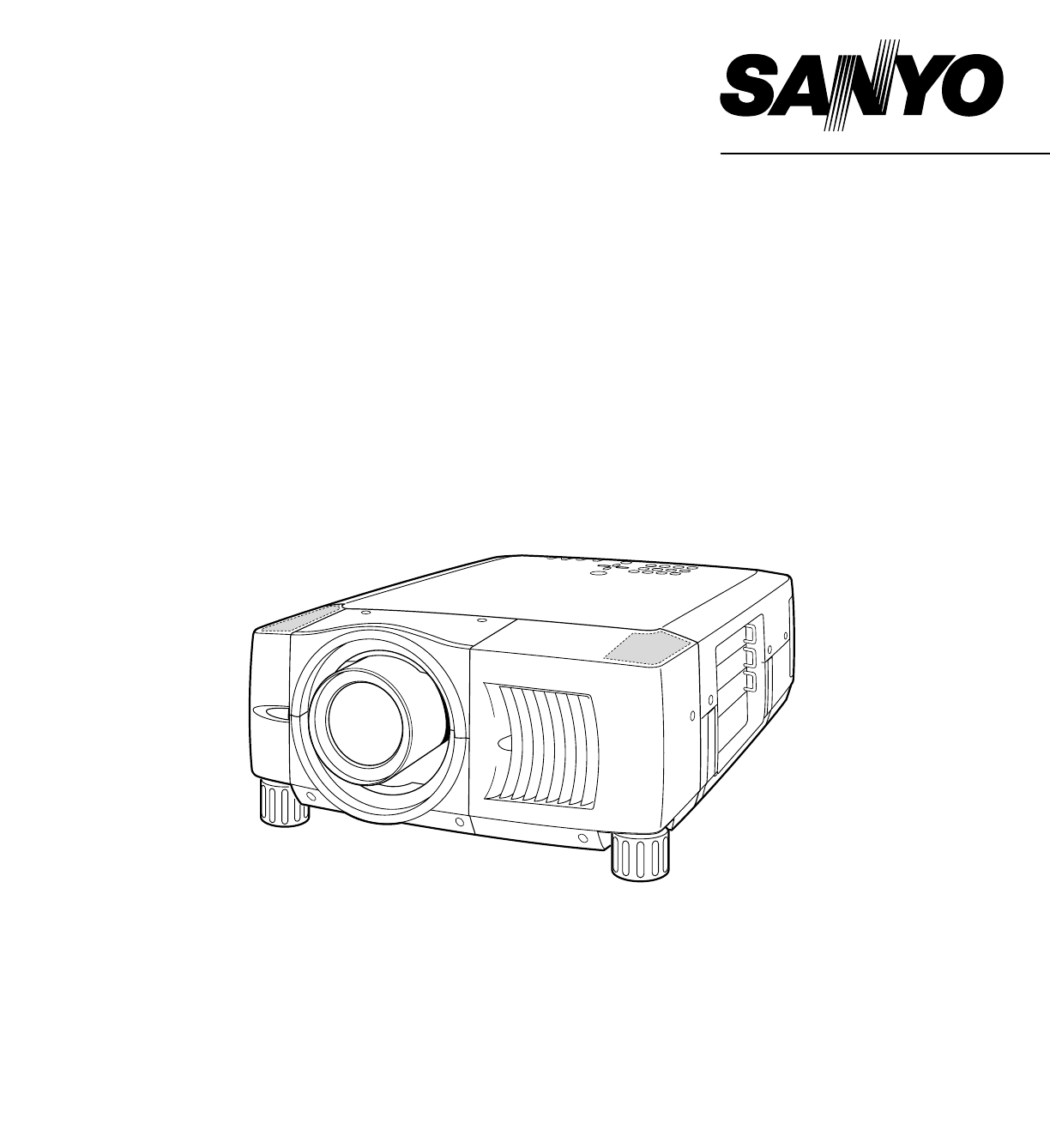
Owner’s ManualPLC-XF30/XF30NLMultimedia ProjectorMODEL ✽ Projection lens is optional.
10PREPARATIONCAUTION IN CARRYING OR TRANSPORTING A PROJECTOR● Do not drop or bump a projector, otherwise damages or malfunctions may result.● When car
11CONNECTING PROJECTORTERMINALS OF PROJECTORThis projector applies various input/output terminals and 3 terminal slots for expansion to tune to divers
12CONNECTING PROJECTORR/Pr G/Y B/Pb H/HV VCONTROL PORTDVIINPUT 1R/C JACKUSBRESET(MONO)(MONO)(MONO)(MONO)AUDIOCONTROL PORTS-VIDEOVIDEO/YCINPUT 2INPUT 3
13CONNECTING PROJECTORConnect an external audioamplifier to these jacks. (Refer to P14, 15.)AUDIO OUTPUT JACKSThis projector uses a micro processor t
14R/Pr G/Y B/Pb H/HV VCONTROL PORTDVIINPUT 1R/C JACKUSBRESET(MONO)(MONO)(MONO)(MONO)AUDIOCONTROL PORTS-VIDEOVIDEO/YCINPUT 2INPUT 3AUDIOAUDIOSERIAL POR
15CONNECTING PROJECTORCONNECTING TO VIDEO EQUIPMENTR/Pr G/Y B/Pb H/HV VCONTROL PORTDVIINPUT 1R/C JACKUSBRESET(MONO)(MONO)(MONO)(MONO)AUDIOCONTROL PORT
16ONON ---- OFFOFFMENUINPUTSELECTLENSSHIFTVOLUMEIMAGEFOCUSAUTOPC ADJ.ZOOMLAMPREPLACEWARNINGTEMP.READYLAMPTOP CONTROLS AND INDICATORSUsed to open or cl
17VOLUMEON-OFFFOCUSZOOMD.ZOOMMENUMUTELASERKEYSTONENO SHOWFREEZEAUTO PC ADJ.IMAGEP-TIMERLOCKINPUT 1/2INPUT 3LENS SHIFTOPERATION OF REMOTE CONTROLONALL
18BEFORE OPERATIONTo insure safe operation, please observe following precautions :● Use (2) AA, UM3 or R06 type alkaline batteries.● Replace two batte
19BEFORE OPERATIONHOW TO OPERATE ON-SCREEN MENUFLOW OF ON-SCREEN MENU OPERATIONDisplay ON-SCREEN MENUPress MENU button to display ON-SCREEN MENU (MENU
2CAUTION : TO REDUCE THE RISK OF ELECTRIC SHOCK, DO NOT REMOVE COVER (OR BACK). NO USER-SERVICEABLE PARTS INSIDE EXCEPT LAMP REPLACEMENT. REFER SERV
20MENU BARPC SYSTEM MENUUsed to selectcomputer system.(Refer to P26, 27)IMAGE ADJUST MENUUsed to adjustcomputer image. [Contrast / Brightness/ White B
21BASIC OPERATIONTURNING ON PROJECTORTURNING OFF PROJECTORTURNING ON / OFF PROJECTOR Power off?Message disappears after 4 seconds.Connect a projector&
22KEYSTONE ADJUSTMENT1Press KEYSTONE ▲/▼ button on Remote Control Unit or selectKeystone on SETTING menu. (Refer to page 39.) Keystonedialog box app
23Press FREEZE button on Remote Control Unit to freeze picture on-screen. To cancel FREEZE function, press FREEZEbutton again or press any other butt
24BASIC OPERATION12Press MENU button and ON-SCREEN MENU will appear. PressPOINT LEFT/RIGHT buttons to move a red frame pointer toSOUND Menu icon. Vol
25COMPUTER INPUTPress MENU button and ON-SCREEN MENU will appear. PressPOINT LEFT/RIGHT button to move a red frame pointer toINPUT Menu icon.Press PO
26COMPUTER INPUTThis projector automatically tunes to most different types of computers based on VGA, SVGA, XGA, SXGA or UXGA (referto “COMPATIBLE COM
27COMPUTER INPUTCOMPATIBLE COMPUTER SPECIFICATIONSBasically this projector can accept a signal from all computers with V, H-Frequency mentioned below
28COMPUTER INPUTPC ADJUSTMENTAUTO PC ADJUSTMENTAuto PC Adjustment function is provided to automatically adjust Fine sync, Total dots and Picture Posit
29COMPUTER INPUTMANUAL PC ADJUSTMENTThis projector can automatically tune to display signals from most personal computers currently distributed. Howe
3SAFETY INSTRUCTIONSAll the safety and operating instructions should be read beforethe product is operated.Read all of the instructions given here and
30NOTE : Display area (H/V) and Full screen cannot be adjusted when“1035i (HDTV)”, “1080i50(HDTV)” or “1080i60 (HDTV)” isselected on PC SYSTEM Menu (P
31COMPUTER INPUTPICTURE IMAGE ADJUSTMENTIMAGE LEVEL SELECT (MENU)Press MENU button and ON-SCREEN MENU will appear. PressPOINT LEFT/RIGHT button to mo
32COMPUTER INPUTPress POINT LEFT/RIGHT buttonsto adjust value.Reset all adjustment to previous figure.ResetStoreCloses IMAGE MENU.QuitOther icons oper
33COMPUTER INPUTPICTURE SCREEN ADJUSTMENTThis projector has a picture screen resize function, which enables you to display desirable image size.Press
34SELECTING INPUT SOURCEPress MENU button and ON-SCREEN MENU will appear. PressPOINT LEFT/RIGHT button to move a red frame pointer toINPUT Menu icon.
35VIDEO INPUTAV SYSTEM MENU (VIDEO OR S-VIDEO)AV SYSTEM MENU (COMPONENT VIDEO)SELECTING VIDEO SYSTEMPress MENU button and ON-SCREEN MENU will appear.
36VIDEO INPUTPICTURE IMAGE ADJUSTMENTIMAGE LEVEL SELECT (MENU)Press MENU button and ON-SCREEN MENU will appear. PressPOINT LEFT/RIGHT button to move
37VIDEO INPUTPress POINT LEFT/RIGHT buttonsto adjust value.Press MENU button and ON-SCREEN MENU will appear. PressPOINT LEFT/RIGHT button(s) to move
38VIDEO INPUTPICTURE SCREEN ADJUSTMENTThis projector has a picture screen resize function, which enables you to display desirable image size.Press MEN
39SETTINGCeilingWhen this function is “On,” picture is top/bottom and left/rightreversed. This function is used to project image from a ceilingmounted
4COMPLIANCESAC Power Cord for the United Kingdom :This cord is already fitted with a moulded plug incorporating a fuse, the value of which is indicate
40SETTINGThis function turns Projection Lamp off when this projector detectssignal interruption and is not used for a certain period in order toreduce
41SETTINGLamp counter resetMove pointer to Lamp counter reset and thenpress SELECT button. Move arrow toreplaced lamp number (Lamp 1 or Lamp2) and th
42APPENDIXOPERATING WIRELESS MOUSEINSTALLATIONWireless Remote Control Unit is not only able to operate this projector but also usable as a wireless mo
43APPENDIXAIR FILTER CARE AND CLEANINGTurn power off, and disconnect AC power cord froman AC outlet.12Air Filter prevents dust from accumulating on a
44APPENDIXLAMP MANAGEMENTThis Projector is equipped with 2 Projection Lamps to ensure brighter image and those lamps are controlled by LampManagement
45APPENDIXCheck number of lamp to be replaced on Lamp StatusDisplay.Loosen 3 screws on Lamp Cover and remove Lamp Cover.(See right figure.)13Loosen 2
● Check audio cable connection from audio input source.● Adjust audio source.● Press VOLUME (+) button.● Press MUTE button.46APPENDIXTROUBLESHOOTINGBe
● Check cable connection between a projector and your computer.● Check mouse setting on your computer.● Turn a projector on before turning on a comput
Accessories48APPENDIX● Specifications are subject to change without notice.TECHNICAL SPECIFICATIONS1.8" TFT Active Matrix type, 3 panelsMulti-med
49APPENDIXCONFIGURATIONS OF TERMINALSTerminal : Mini DIN 8-PINConnect control port (PS/2, Serial or ADB port) on your computer to this terminal with C
5TABLE OF CONTENTSFEATURES AND DESIGN 6BEFORE OPERATION 16COMPUTER MODE 25VIDEO MODE 34SETTING 39APPENDIX 42PREPARATION 7NAME OF EACH PART OF PROJECTO
50APPENDIXVcc- Data+ DataGround1234USB PORT TERMINALPin ConfigurationConnect USB port output terminal of computer or peripheral equipment to this term
51APPENDIX
Printed in JapanPart No. 610 297 5383 (1AA6P1P2846A- MY6A-A)SANYO Electric Co., Ltd
6FEATURES AND DESIGNThis Multimedia Projector is designed with most advanced technology for portability, durability, and ease of use. Thisprojector u
7PREPARATIONNAME OF EACH PART OF PROJECTORBOTTOM BACK HOT AIR EXHAUSTED !Air blown from exhaust vent is hot. Whenusing or installing a projector, fol
8PREPARATIONSETTING-UP PROJECTORThis projector uses nominal input voltages of 100-120 Vor 200-240 V AC. This projector automatically selectscorrect i
9PREPARATIONPOSITIONING PROJECTORBefore setting up a projector, install Projection Lens on Projector.1. Before installation, check where a projector i
Related products and manuals for Projectors Sanyo PLC-XF30NL
 (84 pages)
(100 pages)
(1 pages)
(82 pages)
(58 pages)
(2 pages)
(44 pages)
(90 pages)
(58 pages)
(82 pages)
(23 pages)
(1 pages)
(94 pages)
(24 pages)
(144 pages)
(44 pages)
(84 pages)
(100 pages)
(1 pages)
(82 pages)
(58 pages)
(2 pages)
(44 pages)
(90 pages)
(58 pages)
(82 pages)
(23 pages)
(1 pages)
(94 pages)
(24 pages)
(144 pages)
(44 pages)
© 2020, manymanuals.com. All rights reserved. | 2.248 s |
 Manymanuals.com
 Manymanuals.de
 Manymanuals.fr
 Manymanuals.it
 Manymanuals.pl
 Manymanuals.cz
 Manymanuals.es
 Manymanuals-pt.com
Comments to this Manuals