Sanyo KS1872 User Manual
Browse online or download User Manual for Door intercom systems Sanyo KS1872. Sanyo KS1872 User's Manual
- Page / 25
- Table of contents
- BOOKMARKS
- INSTALLATION INSTRUCTIONS 1
- Please Read Before Starting 2
- IMPORTANT! 2
- 1. General 3
- About 1'4" (40 cm) 5
- Rear panel 7
- 3/16" 8
- (4.8 mm) dia. hole 8
- Rawl plug 8
- OUTDOOR 11
- Strip 15/16" (25 mm) 13
- Strip 3/8" (10 mm) 13
- Padding material 14
- 5. Refrigerant Tubing 18
- Insulated tubes 19
- Apply putty here 19
- 6. Air Purging 20
- Pump Down 23
- 8. Address Switch 25
Summary of Contents
85264189988000 © SANYO 2006In CanadaSANYO FISHER COMPANY SANYO Canada Inc.A DIVISION OF SANYO NORTH AMERICA CORPORATION 300 Applewood Crescent, Conc
103-5. Shape the Indoor Side Tubing(1) Arrangement of tubing by directiona) Right or left tubingCut out the corner of the right/left frame with ahack
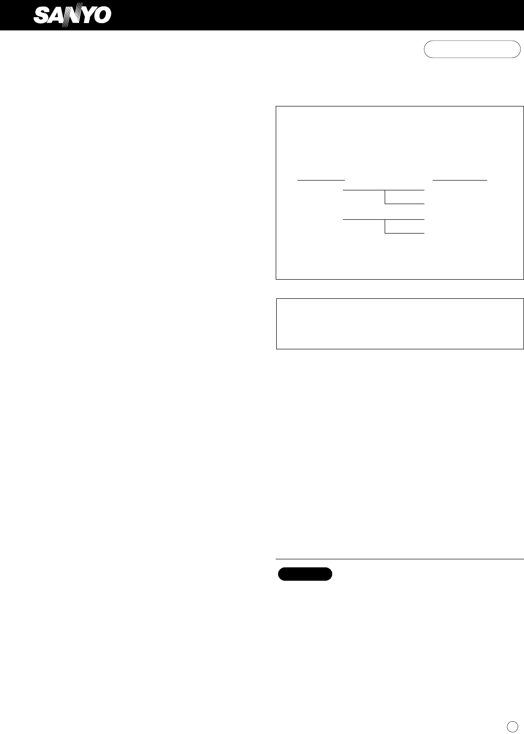
11(A)+(B) (A) Power Supply Wiring Length (ft) (C) ControlFuse or Circuit AWG(B) Power Line Length (ft) Line Length (ft)Model (#14) (#12) (#14)Breaker
123-8. Wiring Instructions for Inter-unit Connections(1) Insert the inter-unit wiring (according to local codes)into the through-the-wall PVC pipe. R
13When connecting each power wire to the correspondingterminal, follow the instructions “How to connect wiringto the terminal” and fasten the wire sec
143-9. Mounting(1) To install the indoor unit, mount the indoor unit ontothe 2 tabs on the upper part of the rear plate. (2) Hold down the air discha
15Hole in wallBent partNarrow tubeWide tubeRear panelFig. 38Drain capDrain hoseFig. 39I Left-side tubing(1) Lead the tubing and drain hose through the
16To unmount indoor unitPress the 2 LL marks on the lower part of the indoor unitand unlatch the tabs. Then lift the indoor unit andunmount. (Fig. 42)
174. How to Install the Outdoor UnitFirst refer to Section 2. Installation Site Selection.4-1. Wiring Instructions for the Outdoor UnitRegulations o
185. Refrigerant Tubing5-1. Use of the Flaring MethodMany of the conventional split system air conditionersemploy the flaring method to connect refr
195-4. Connecting Tubing between Indoor and Outdoor Unitsa) Tightly connect the indoor side refrigerant tubing exten-ded from the wall with the outdoo
2IMPORTANT! Please Read Before StartingThis air conditioning system meets strict safety and operatingstandards. As the installer or service person, it
206. Air PurgingAir and moisture remaining in the refrigerant systemhave undesirable effects as indicated below. Therefore,they must be purged comple
21(5) With the vacuum pump still running, close the “Lo”knob of the manifold valve. Then stop the vacuumpump.(6) With the accessory hex wrench, turn t
22How to Test Run the Air ConditionerAfter turning on power to the air conditioner, use the remotecontroller and follow the steps below to conduct the
23I Pump DownPump down means collecting all refrigerant gas in thesystem back into the outdoor unit without losing any ofthe gas. Pump down is used wh
247. Remote Control Unit Installation PositionThe remote control unit can be operated from either anon-fixed position or a wall-mounted position.To e
258. Address Switch8-1. Address Setting of the Remote Control UnitThe address can be set in order to prevent interferencebetween remote controllers
31. GeneralThis booklet briefly outlines where and how to install theair conditioning system. Please read over the entire setof instructions for the
41-5. Additional Materials Required for Installation1. Refrigeration (armored) tape2. Insulated staples or clamps for connecting wire(See local codes
52-2. Outdoor UnitAVOID:G heat sources, exhaust fans, etc. (Fig. 4)G damp, humid or uneven locations.DO:G choose a place as cool as possible.G choose
62-3. Baffle Plate for the Outdoor Unit(CLxx models only)It is recommended to use baffle plates for modelsCL1872 and CL2472. The baffle plates are no
7Set screw only for transportationFig. 6Rear panelmarksFig. 7Left tubingRight tubingDownward tubingRight-rear tubing(recommended)Left-rear tubingFig.
8IndoorsideOutdoorsideHole should be made at a slight downward slant to theoutdoor side.NOTEFig. 10Plastic coverINSIDE OUTSIDEWallSlightanglePVC pipe(
93-4. Remove the Grille to Install the Indoor UnitBasically, these models can be installed and wired with-out removing the grille. If access to any i
© 2020, manymanuals.com. All rights reserved. | 1.982 s |
 Manymanuals.com
 Manymanuals.de
 Manymanuals.fr
 Manymanuals.it
 Manymanuals.pl
 Manymanuals.cz
 Manymanuals.es
 Manymanuals-pt.com
Comments to this Manuals