Sanyo MDF-C8V User Manual
Browse online or download User Manual for Fridge-freezers Sanyo MDF-C8V. Sanyo MDF-C8V User's Manual [en]
- Page / 92
- Table of contents
- TROUBLESHOOTING
- BOOKMARKS
- Effective models 2
- Contents 3
- Features 4
- Specifications 5
- 㧨/&(%8㧪 8
- Refrigeration circuit diagram 9
- Ex. tank 10
- Ex. capillary 10
- Place to fit AT sensor 10
- Cooling unit parts 11
- Components on PCB 12
- Electrical Parts 13
- Specification of sensor 14
- Wiring diagram 15
- Circuit diagram 16
- Connection on PCB 17
- Control specification 18
- Parts layout 26
- Test Data 29
- 㪈㪆㪉㪟䇭㪘㫀㫉 30
- 㪬㫅㫀㫋䇭㪧㫉㪼㫊㫊㫌㫉㪼䋨㫇㫌㫃㫃㪄㪻㫆㫎㫅㪀 31
- 㪉㪊㪇㪭䇭㪌㪇㪟㫑䇭㪘㪫㪊㪌㷄䇭㪥㫆䇭㫃㫆㪸㪻 31
- 㪧㫆㫎㪼㫉䇭㪚㫆㫅㫊㫌㫄㫇㫋㫀㫆㫅䋨㫇㫌㫃㫃㪄㪻㫆㫎㫅㪀 32
- Instruction manual 35
- Ultra-Low Temperature Freezer 36
- INSTRUCTION MANUAL 36
- CONTENTS 37
- INTRODUCTION 38
- ENVIRONMENTAL CONDITIONS 43
- FREEZER COMPONENTS 44
- INSTALLATION SITE 47
- INSTALLATION 48
- START-UP OF UNIT 49
- KEY LOCK FUNCTION 50
- ALARM TEMPERATURE SETTING 51
- REMOTE ALARM TERMINAL 55
- ROUTINE MAINTENANCE 57
- REPLACEMENT OF BATTERY 59
- TROUBLESHOOTING 60
- DISPOSAL OF UNIT 61
- WARNING 66
- Installation of MTR-85H 67
- Installation of MTR-G85 69
- BACK-UP SYSTEM (OPTION) 71
- SPECIFICATIONS 73
- PERFORMANCE 74
- CAUTION 75
- Safety check sheet 75
- Back-up System for 76
- COMPONENTS LIST 81
- CONTROL PANEL 89
- TRIAL OPERATION 90
- PERFORMANCE 91
- JK1659-150B 92
Summary of Contents
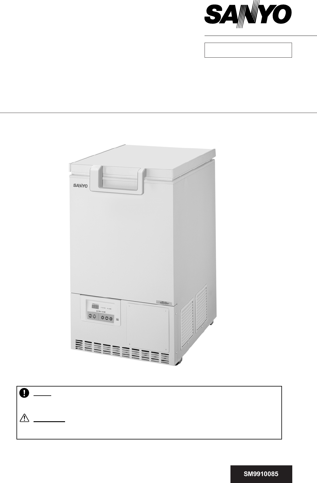
SANYO Electric Co., Ltd.Biomedical Business UnitService ManualUltra-Low Temperature FreezerMDF-C8VFILE No. RoHS This product does not contain any
7Refrigeration circuit welding points 䌄䌄䌔䋱䌅䌘䌏䌅䌘䌉䌐䋲䌐䋳䌐䋱 䌔䋲䌔䋳䌔䌚㩷䌔䌙㩷Ex. tank Ex. capillary Place to fit AT sensor 㪚㪈㩷䌆䌂䌆䌁㪚㪉㩷㪚㪊㩷㪚㪋㩷㪚㪌㩷㪚㪍㩷㪚㪎㩷㪚㪈㪋㩷㪚㪈㪌㩷㪚㪏㩷㪚㪐㩷
8 Cooling unit parts <MDF-C8V> Item Specifications Compressor 115V, 60Hz Type: C-2SN400L2W Compressor code: 807 780 22 220/230/240V,5
9 Components on PCB
10CompressorType C-2SN400L2W C-2SN400L5WCompressor code 807 780 22 807 780 25Rated voltage (50/60Hz) 㱢1, 110~115V, 60Hz ij1, 220~240V, 50/60HzWinding r
11 Specification of sensor Following shows the relation between temperatures of temp. sensor (Pt1000ȍ) and resistance value. Temperature (℃) Resis
12 Wiring diagram
13 Circuit diagram
14 Connection on PCB Following is the explanation of connections on Main PCB. Connector Connects to Usage Voltage CN1 Switching power supply T
15㩷 Control specification 1. Key and Switch BUZZER : In alarm condition, buzzer stops sounding with this key pressed. Remote alarm ou
16 B) Function mode Setting range : 00~33 Display range : 00~39 00, 04, 08, 13, 15, 16, 18, 19, 20, 26, 27, 31 and 33 are unav
Effective models This service manual is effective following models. Model name Product code Voltage and Frequency MDF-C8V 823 187 51 115V
177. Function mode F00 Automatically revert to PV display F01 SVH (high temp. alarm SV) setting F02 SVL (low temp. alarm SV) setting F03 B
18 F04: <Purpose> Simply passing through if entered by mistake. <Operation> Press SET key in “F04” displayed to revert to PV displ
19 F16: <Purpose> Simply passing through if entered by mistake. <Operation> Press SET key in “F16” displayed to revert to PV displ
20 F25: <Purpose> Alarm auto recovery time setting <Operation> Input F25 and press SET key to display “030” (initial). Change to t
2110. Remote alarm terminal In normal condition: 㸣 In alarm condition & power failure : Remote alarm contact: N.O. N.C. 㸣 Remote alarm co
2213. Fan motor operation and compressor protection Fan motor operation : 1.When the temperature in Comp. sensor is lower than 20㷄; Fan motor tur
23<Temp. sensor PT-1000>Comp.sensor<Fan><Battery><Control panel>Battery cover<Back side of Control panel>Display PCBCont
24<How to access the Main PCB>1. Catch the pick by screwdriver to pull the panel out.2.Loosen tie band to set cables free. Pull Electric BOX out
25<Lower back side> <Remote alarm>Battery switchEx.tankTemp.control relay Fan relayPower cordBreaker switchRunning capacitorStarting capac
26 Test Data Note: All data is the reference only. 㪫㪼㫄㫇㪼㫉㪸㫋㫌㫉㪼㩷㪺㪿㪸㫉㪸㪺㫋㪼㫉㫀㫊㫋㫀㪺㫊䋨㫇㫌㫃㫃㪄㪻㫆㫎㫅㪀㪈㪈㪌㪭䇭㪍㪇㪟㫑䇭㪘㪫㪊㪇㷄䇭㪥㫆䇭㫃㫆㪸㪻㪄㪈㪇㪇㪄㪏㪇㪄㪍㪇㪄㪋㪇㪄㪉㪇㪇㪉㪇㪋㪇㪇㪈㪉
Contents Page Features ----------------------------------------------------- 1Specifications ----------------------------------------------------- 2
27㪫㪼㫄㫇㪼㫉㪸㫋㫌㫉㪼㩷㪺㪿㪸㫉㪸㪺㫋㪼㫉㫀㫊㫋㫀㪺㫊䋨㫇㫌㫃㫃㪄㫌㫇㪀䇭㪘㪫㪊㪇㷄䇭㪥㫆䇭㫃㫆㪸㪻㪄㪈㪇㪇㪄㪏㪇㪄㪍㪇㪄㪋㪇㪄㪉㪇㪇㪉㪇㪋㪇㪇㪈㪉㪊㪋㪌㪍㪫㫀㫄㪼㪲㪿㫆㫌㫉㪴㪫㪼㫄㫇㪼㫉㪸㫋㫌㫉㪼㪲㷄㪴㪈㪆㪉㪟䇭㪘㫀㫉
28㪬㫅㫀㫋䇭㪧㫉㪼㫊㫊㫌㫉㪼䋨㫇㫌㫃㫃㪄㪻㫆㫎㫅㪀㪉㪊㪇㪭䇭㪌㪇㪟㫑䇭㪘㪫㪊㪌㷄䇭㪥㫆䇭㫃㫆㪸㪻㪇㪇㪅㪌㪈㪈㪅㪌㪉㪉㪅㪌㪊㪊㪅㪌㪋㪇㪈㪉㪊㪋㪌㪍㪎㪏㪐㪈㪇㪈㪈㪈㪉㪫㫀㫄㪼㪲㪿㫆㫌㫉㪴㪧㫉㪼㫊㫊㫌㫉㪼㪲㪤㪧㪸㪴㪧䌤㪧䌳㪬㫅㫀㫋䇭㪧㫉㪼㫊㫊㫌㫉㪼䋨㫇㫌㫃㫃㪄㪻㫆㫎㫅㪀㪈㪈㪌㪭䇭㪍㪇㪟㫑䇭㪘㪫㪊㪌㷄䇭㪥
29㪧㫆㫎㪼㫉䇭㪚㫆㫅㫊㫌㫄㫇㫋㫀㫆㫅䋨㫇㫌㫃㫃㪄㪻㫆㫎㫅㪀㪈㪈㪌㪭䇭㪍㪇㪟㫑䇭㪘㪫㪊㪌㷄䇭㪥㫆䇭㫃㫆㪸㪻㪇㪌㪇㪈㪇㪇㪈㪌㪇㪉㪇㪇㪉㪌㪇㪊㪇㪇㪊㪌㪇㪋㪇㪇㪋㪌㪇㪌㪇㪇㪇㪈㪉㪊㪋㪌㪍㪎㪏㪐㪈㪇㪈㪈㪈㪉㪫㫀㫄㪼㪲㪿㫆㫌㫉㪴㪧㫆㫎㪼㫉䇭㪺㫆㫅㫊㫌㫄㫇㫌䌴㫀㫆㫅䇭㪲㪮㪴㪇㪇㪅㪌㪈㪈㪅㪌㪉㪉㪅㪌㪊㪊㪅㪌㪋㪋㪅
301. Preparation* Refrigerant [MU-N48]* Connector for charging pipe (if necessary)2. Procedures1) Pull vacuum in refrigeration circuitPull vacuum by p
313) Charge of refrigerantStop vacuum pump operation.Open the valve of tank to charge refrigerantwith approx. 0.2~0.5 Mpa/G.4) Pipe pinching in High p
32 Instruction manual xThis section is extracted and printed from Instruction Manual. xIf you find out “Refer to page ƔƔ” in them, this page m
33MDF-C8VUltra-Low Temperature FreezerINSTRUCTION MANUAL
341 CONTENTS INTRODUCTION P. 2 PRECAUTIONS FOR SAFE OPERATION P. 3 ENVIRONMENTAL CONDITIONS P. 7 FREEZER COMPONENTS P. 8
352 INTRODUCTION Ŷ Read this manual carefully before using the appliance and follow the instructions for safety operation. Ŷ Sanyo never guarante
363 PRECAUTIONS FOR SAFE OPERATION It is imperative that the user complies with this manual as it contains important safety advice. Items and pr
1 Features 䂓㩷 Space saving freezer for personal use - ‘Glass wool’ core is newly adopted for insulation - Width 550mm for minimal installation
374 PRECAUTIONS FOR SAFE OPERATION Do not use the unit outdoors. Current leakage or electric shock may result if the unit is exposed to rai
385 PRECAUTIONS FOR SAFE OPERATION Ensure you do not inhale or consume medication or aerosols from around the unit at the time of maintenance
396 PRECAUTIONS FOR SAFE OPERATION Use a dedicated power source (a dedicated circuit with a breaker) as indicated on the rating label attached
407 ENVIRONMENTAL CONDITIONS This equipment is designed to be safe at least under the following conditions (based on the IEC 1010-1): Ŷ Indoor u
418 FREEZER COMPONENTS 1312511 12 36 7 854109
429 FREEZER COMPONENTS 1. Lock: By turning to 180 degree to clockwise with a key, the door can be locked. 2. Door: Top hinged type. To
4310 FREEZER COMPONENTS Control panel 1. Alarm buzzer stop key (BUZZER): To silence the audible alarm, press this key. The a
4411 INSTALLATION SITE To operate this unit properly and to obtain maximum performance, install the unit in a location with the following conditi
4512 INSTALLATION 1. Removing the packaging materials and tapes Remove all transportation packaging materials and tapes. Open the doors and ven
4613 START-UP OF UNIT Follow the procedures for the initial and consequent operations of the unit. 1. Connect the power cord to the dedicated ou
2 Specifications ŶStructural specifications Item Specifications External dimensions W 550 × D 685 × H 945(mm) Internal dimensions W 405 × D 490 ×
4714 CHAMBER TEMPERATURE SETTING Table 1 shows the basic procedure for setting the chamber temperature. Perform key operations in the sequence
4815 ALARM TEMPERATURE SETTING This unit is provided with the high and low temperature alarm and the temperature at which the alarm is activated
4916 ALARM TEMPERATURE SETTING Table 4 Procedure for setting low temperature alarm Description of operation Key operated Indication after op
5017 SETTING OF ALARM RESUME TIME The alarm buzzer is silenced by pressing alarm buzzer stop key (BUZZER) key on the control panel during alar
5118 CHANGE OF COMPRESSOR DELAY TIME The delay time of the compressor can be changed to reduce the load on the power line and to facilitate the
5219 REMOTE ALARM TERMINAL WARNING Always disconnect the power supply cord before connecting an alarm device to the remote alarm terminal. The t
5320 ALARMS & SAFETY FUNCTIONS This unit has the alarms and safety functions shown in Table 7, and also self diagnostic functions. Table 7
5421 ROUTINE MAINTENANCE WARNING Always disconnect the power supply to the unit prior to any repair or maintenance of the unit in order to preven
5522 ROUTINE MAINTENANCE Battery The battery for power failure alarm is an article for consumption. The battery life is approximately 3 years.
5623 REPLACEMENT OF BATTERY Location of a nickel-metal-hydride battery This unit is provided a nickel-metal-hydride battery for the power failure
3ŶControl specifications Item Specifications Cooling performance -80℃ (1/2H temp, AT 30℃, no load) Temperature control range -60℃~-80℃(AT5~30℃, no
5724 TROUBLESHOOTING If the unit malfunctions, check out the following before calling for service. Malfunction Check/Remedy The freezer does not r
5825 DISPOSAL OF UNIT WARNING If the unit is to be stored unused in an unsupervised area for an extended period ensure that children do not have
5926 DISPOSAL OF UNIT Waste Electrical and Electronic Equipment (WEEE) Directive-2002/96/EC (English) Your SANYO product is designed
6027 DISPOSAL OF UNIT (French) Votre produit Sanyo est conçu et fabriqué avec des matèriels et des composants de qualité supérieure
6128 DISPOSAL OF UNIT (Portuguese) O seu produto SANYO foi concebido e produzido com materiais e componentes de alta qualidade que po
6229 DISPOSAL OF UNIT (Dutch) Sanyo producten zijn ontwikkeld en gefabriceerd uit eerste kwaliteit materialen, de onderdelen kunnen w
6330 TEMPERATURE RECORDER (OPTION) WARNING Always disconnect the power supply to the unit prior to attachment of a temperature recorder in order t
6431 TEMPERATURE RECORDER (OPTION) Installation of MTR-85H 1. Remove 4 screws (A, B, C, D) on the side of the front panel to take off the fron
6532 TEMPERATURE RECORDER (OPTION) 6. Attach the sensor cover to the right side of the chamber with 2 screws on the chamber wall (Fig. 4)
6633 TEMPERATURE RECORDER (OPTION) Installation of MTR-G85 1. Remove 4 screws (A, B, C, D) on the side of the front panel to take off the fron
4ŶPerformance specifications Cooling performance -80℃ (ambient temperature; 30℃,no load) Temperature control range -60℃ to -80℃(ambient temperature
6734 TEMPERATURE RECORDER (OPTION) 6. Attach the sensor cover to the right side of the chamber with 2 screws on the chamber wall (Fig. 4) 7. Seal
6835 BACK-UP SYSTEM (OPTION) This freezer can be provided with a back-up system (CVK-UB4) which is available as an optional component. For the
6936 BACK-UP SYSTEM (OPTION) With the back-up system (CVK-UB4), the freezer prevents the chamber temperature from going up by injecting the liquid
7037 SPECIFICATIONS Name Ultra-Low Temperature Freezer Model MDF-C8V External dimensions W550 x D685 (+83)* x H945 (mm) Internal dimensions W
7138 PERFORMANCE Cooling performance -80oC (ambient temperature; 30oC, no load) Temperature control range -60oC to -80oC (ambient temperature; 3
7239 CAUTION Please fill in this form before servicing. Hand over this form to the service engineer to keep for his and your safety. Safety c
73CVK-UB4CVK-UB4(I)Back-up System for Ultra-Low Temperature FreezerINSTRUCTION MANUAL
741 CONTENTS INTRODUCTION P. 2 PRECAUTIONS FOR SAFE OPERATION P. 3 COMPONENTS LIST P. 5 INSTALLATION Assembling of
752 INTRODUCTION Ŷ Read this manual carefully before using the appliance and follow the instructions for safety operation. Ŷ Sanyo never guarante
763 PRECAUTIONS FOR SAFE OPERATION It is imperative that the user complies with this manual as it contains important safety advice. Items and pro
5 Dimensions 405490R255505885294542588735727685 33㧨/&(%8㧪
774 PRECAUTIONS FOR SAFE OPERATION Only qualified engineers or service personnel should install this system. The installation by unqualified
785 COMPONENTS LIST Confirm that the accessories of the table 1 are gathered. Report it to the dealer or the sales if there is a problem in pac
796 COMPONENTS LIST The continuation of the table 1 No. PARTS NAME Q’ TY APPEARANCE THE EXPLANATION OF THE USE 9 LABEL 1 It is put near the
807 COMPONENTS LIST The continuation of the table 1 No. PARTS NAME Q’ TY APPEARANCE THE EXPLANATION OF THE USE 20 WIRING ASS’Y BP 1 It is ha
818 INSTALLATION Assembling of the solenoid valve 1. The joint nut on the outlet side of the CO2 solenoid valve is removed. The valve outlet
829 INSTALLATION Installation of the door switch 1.㩷 Spacer and a door switch mounting plate are fixed on the hole of the left side (upside)
8310 INSTALLATION Installation of the back-up kit 1.㩷 The slit (bottom right rear side) which freezer is being fitted up with, a rear cover,
8411 INSTALLATION 6. The sensor cover inside freezer chamber is removed, and the thermostat sensor part of the back-up system is inserted into th
8512 INSTALLATION Wiring 1. Harness (a white connector) from the solenoid valve is connected to the connector of the upp
8613 CONTROL PANEL 1. Power switch of back-up system (BACKUP) When turning on the system, the back-up stand-by on the door switch a
6 Refrigeration circuit diagram
8714 TRIAL OPERATION Following is the procedures for the trial operation of the back-up system. Read an instruction manual enclosed with a ultra-
8815 SPECIFICATIONS Name Back-up System for Ultra-Low Temperature Freezer Model CVK-UB4 CVK-UB4(I) Outer dimensions W286 x D87 x H520 mm Applica
1JK1659-150B
Related products and manuals for Fridge-freezers Sanyo MDF-C8V


 (8 pages)
© 2020, manymanuals.com. All rights reserved. | 1.668 s |
 Manymanuals.com
 Manymanuals.de
 Manymanuals.fr
 Manymanuals.it
 Manymanuals.pl
 Manymanuals.cz
 Manymanuals.es
 Manymanuals-pt.com
Comments to this Manuals