Sanyo DSR-2108 User Manual
Browse online or download User Manual for Car DVR Sanyo DSR-2108. Sanyo DSR-2108 User Manual
- Page / 92
- Table of contents
- BOOKMARKS
Rated. / 5. Based on customer reviews
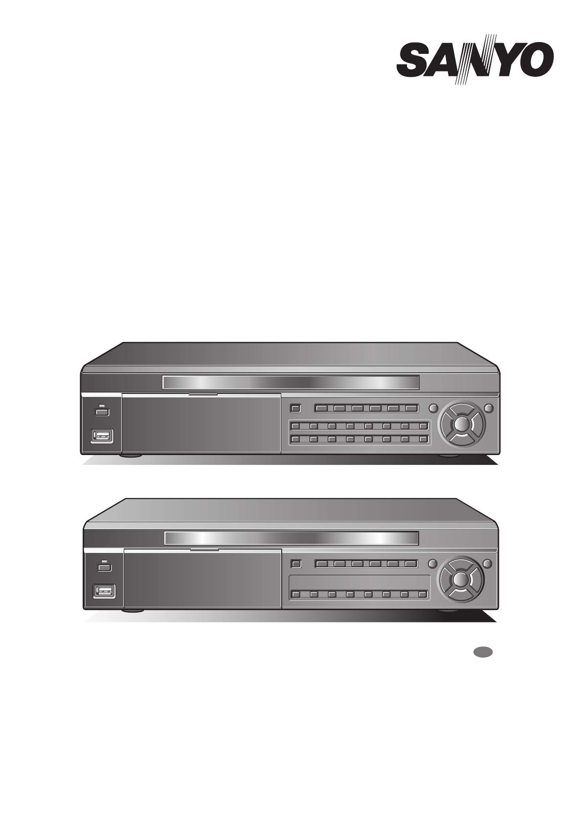
DSR-2116
DSR-2108
About this manual
Before installing and using this unit, please read this manual carefully.
Be sure to keep it handy for later reference.
INSTRUCTION MANUAL
Digital Video Recorder
with Multiplexer Function
DSR-2108
DSR-2116
GB
● Refer to the included CD-ROM for the German, French, Spanish and Italian “INSTRUCTION MANUAL”.
● Die “BEDIENUNGSANLEITUNG” in den Sprachen Deutsch, Französisch, Spanisch und Italienisch
finden Sie auf der beiliegenden CD-ROM.
● Utilisez le CD-ROM fourni pour consulter le “MANUEL D’INSTRUCTIONS” en allemand, français,
espagnol et italien.
● Consulte en el CD-ROM suministrado el “MANUAL DE INSTRUCCIONES” en alemán, francés, español e
italiano.
● Per il “MANUALE DI ISTRUZIONI” in Tedesco, Francese, Spagnolo e Italiano, fare riferimento al
CD-ROM allegato.
L8HBT_WA(DSR-2116_2108)(GB).book 1 ページ 2009年5月27日 水曜日 午後4時50分
- DSR-2116 1
- DSR-2108 1
- Table of Contents 2
- Safety precautions 3
- Main Features 8
- Main parts 8
- Accessories 8
- About the split 9
- Names and functions of parts 10
- Rear panel 11
- Basic connections 11
- Network connection (LAN) 12
- RS-485/422 13
- Switching the power on / off 14
- Pre-operation preparation 15
- Monitoring the camera videos 19
- Operating the PTZ dome camera 21
- Recording 23
- POWERMODEAUTOMENU 25
- Playing back recorded videos 28
- 2009/04/12 10:00:00 30
- 2009/04/12 11:00:00 30
- 2009/04/12 11:25:00 30
- 2009/05/03 09:04:54 33
- 2009/04/14 17:25:37 34
- Setting the security lock 35
- MAIN MENU 36
- LIVE settings 38
- RECORD settings 42
- SYSTEM settings 44
- NETWORK settings 49
- IP ADDRESS 51
- 172.016.001.052 51
- HDD SET settings 54
- SERVICE settings 56
- Operations using the Network 57
- Connecting to this unit 59
- Main screen basic operations 62
- Search mode operations 66
- Setup menu settings 69
- Remote Setup 73
- Input example: 83
- Video display area 83
- Operation 83
- Log window 83
- Time scale panel 84
- Slide knob 84
- • f button 86
- • e button 86
- • button 86
- Specifications 87
- SANYO Electric Co., Ltd 92
Summary of Contents
Page 1 - DSR-2108
DSR-2116DSR-2108About this manualBefore installing and using this unit, please read this manual carefully.Be sure to keep it handy for later reference
Page 2 - Table of Contents
3Names and functions of partsFront panel1 Power button and indicator ( )2 USB terminal (USB) (Exclusively for 2.0) (P26)To save video, connect a USB m
Page 3 - Safety precautions
4Names of each part and connectionsRear panel1 Video input terminal (VIDEO IN/LOOP OUT)2 Video output terminal (S-VIDEO)3 Monitor 2 video output termi
Page 4
Names of each part and connections5b Using the switching hubUse a 10BASE-T/100BASE-TX CAT 5 LAN cable.When controlling the network, connect to hubs su
Page 5
Names of each part and connections6Remote systems such as system controllers and PTZ dome cameras are connected to the RS-485 control terminal.Check t
Page 6
7Switching the power on / off1Connect the power cable to the outlet.Turn on the electricity, the power indicator lights in orange (standby).2Press the
Page 7
8Pre-operation preparationUpon turning the power on, live video is displayed in the multi screen format.• The screen display can be hidden except for
Page 8 - Accessories
Pre-operation preparation9If the television system of the camera to be connected and the type of monitor differ, live videos cannot be monitored on th
Page 9 - About the split
Pre-operation preparation103Press the control button (~) twice and select the "SYSTEM", press the ENTER button.The SYSTEM settings screen is
Page 10 - Names and functions of parts
Pre-operation preparation119Select "CONFIRM" using the control button (}~) and press the ENTER button.The unit automatically restarts, the i
Page 11 - Basic connections
12Monitoring the camera videosDisplays the video of the camera specified using the channel selection button on single-screen.Example: Displaying camer
Page 12 - Network connection (LAN)
iTable of ContentsSafety precautions . . . . . . . . . . . . . . . . . . . . . . . . . . . . . . . . . . . . . iiThese precautions must be followed f
Page 13 - RS-485/422
Monitoring the camera videos13Displays the videos of 16 or 9 cameras simultaneously. 1Press the MULTI button.The videos of camera 1 - 16 are displayed
Page 14 - Switching the power on / off
14Operating the PTZ dome cameraPan/Tilt, Zoom/Focus operations are possible from this unit when a coaxial superimposed type (COAX) camera is connected
Page 15 - Pre-operation preparation
Operating the PTZ dome camera15b Iris/Tour/Sequence operations1 Select "IRIS/TOUR/SEQUENCE" using the control button ({|) and press the ENTE
Page 16
16RecordingThis unit allows the following recording modes.Select the recording mode, recording resolution, frame rate and video quality from "REC
Page 17
Recording171Recording starts automatically when this unit is turned on."C" is displayed on the screen. The connected cameras are simultaneou
Page 18
Recording18An external sensor can be connected to each channel.1Connecting an external switch to an external alarm input terminal.2Set the following i
Page 19 - Monitoring the camera videos
Recording191Adjusting the following settings using the control button ({|}~).2Select "RECORDING" using the control button ({|) and select &q
Page 20
Recording20b Copying a set recording schedule to other channels1Set the channel 1 schedule and press the EXIT/STOP button.The RECORD screen is display
Page 21 - Operating the PTZ dome camera
21Playing back recorded videosThe following recorded videos searching methods are available.SEARCHEVENT SEARCHTIMELINE SEARCHT/D SEARCHGO FIRSTGO LAST
Page 22
Playing back recorded videos221Press the SEARCH button.The menu screen is displayed.2Select "EVENT SEARCH" using the control button ({|) and
Page 23 - Recording
iiSafety precautionsCAUTION: Changes or modifications not expressly approved by the manufacturer may void the user’s authority to operate this equipme
Page 24
Playing back recorded videos231Press the SEARCH button.The search menu screen is displayed.2Select "TIMELINE SEARCH" using the control butto
Page 25 - POWERMODEAUTOMENU
Playing back recorded videos241Press the SEARCH button.The search menu screen is displayed.2Select "T/D SEARCH" using the control button ({|
Page 26
Playing back recorded videos25Perform the mark operation of the desired live video. The marked event can be selected and displayed from the list (date
Page 27
26Copying recorded video to recording mediaNecessary video can be selected and copied to USB memory or to a DVD-R, CD-R/RW.Insert the recording media
Page 28 - Playing back recorded videos
Copying recorded video to recording media27The image to be copied can be selected on still and moving images.1While playing back the recorded video pr
Page 29
28Setting the security lockSetting a security lock locks all the operation buttons of this unit.b Setting a security lock1Press the EXIT/STOP button f
Page 30 - 2009/04/12 11:25:00
29Configuration and function of the Menu settingsSERVICESAVE SETUP TO A USBLOAD SETUP FROM A USBDISK INFOLIVEOSD ONSEQUENCE ONSEQUENCE-DWELL TIME 2 SE
Page 31
Configuration and function of the Menu settings30b Basic operations of the MAIN MENU1Press the MENU button.The PASSWORD input screen is displayed.2Inp
Page 32
31LIVE settingsPress the MENU button and enter the ADMIN PASSWORD.The MAIN MENU is displayed, select "LIVE" using the control button ({|}~).
Page 33 - 2009/05/03 09:04:54
LIVE settings32To set the video settings on each channel.Select an item for each setting using the control button ({|) and select a setting value usin
Page 34 - 2009/04/14 17:25:37
Safety precautionsiiiThese precautions must be followed for safety reasons.Warningb Do not use if the unit emits smoke, strange sounds are heard or od
Page 35 - Setting the security lock
LIVE settings332 Select the setting position (4 positions) using the control button (}~).3 Select the input terminal number (1 - 16) using the control
Page 36 - MAIN MENU
LIVE settings34● Setting the SEQUENCESets whether the output video automatically switches to the MON2 terminal.1 Select "SEQUENCE" using the
Page 37
35RECORD settingsPress the MENU button and enter the password.The MAIN MENU is displayed, select "RECORD" using the control button ({|}~).To
Page 38 - LIVE settings
RECORD settings36• ALARM (P18)Recording is performed as soon as a sensor device connected to the external alarm input terminal (ALARM IN) of this unit
Page 39
37SYSTEM settingsPress the MENU button and enter the password.The MAIN MENU is displayed, select "SYSTEM" using the control button ({|}~).Al
Page 40
SYSTEM settings38To set a password to perform menu settings, real time recording, search and playback. The initial value is "1111".Memo: If
Page 41
SYSTEM settings39b Restoring the password input1Press the MENU button, select SYSTEM and press the ENTER button.2Select "ADMIN PASSWORD" usi
Page 42 - RECORD settings
SYSTEM settings40Refer to "Setting the clock (CLOCK SET)". (P9)Refer to "Setting the clock (CLOCK SET)". (P9)To be set when device
Page 43
SYSTEM settings41Allows to set an ID number on the supplied remote control and use it as an exclusive remote control when multiple units are connected
Page 44 - SYSTEM settings
42NETWORK settingsPress the MENU button and input the password.The MAIN MENU is displayed, select "NETWORK" using the control button ({|}~).
Page 45
Safety precautionsivWarningb Do not use during thunder/thunder storms.Do not use during thunder/thunder storms. Never touch the connection cable durin
Page 46
NETWORK settings43Select "NETWORK TYPE" to be connected, and set each setting. Consult the network manager for all necessary information.1Se
Page 47
NETWORK settings44b If selecting LAN1 Select "IP" using the control button ({|) and press the ENTER button.The IP ADDRESS input screen is di
Page 48
NETWORK settings455Enter the "USER ID" and "PASSWORD" confirmed on the DDNS SERVER SET screen and click the Login button.The domai
Page 49 - NETWORK settings
NETWORK settings46•MAIL TOTo set the destination mail address.Example:• MAIL SERVERSets the mail server name, as well as the USER and PASSWORD.Example
Page 50
47HDD SET settingsPress the MENU button and input the password.The MAIN MENU is displayed, select "HDD SET" using the control button ({|}~).
Page 51 - 172.016.001.052
HDD SET settings48Allows the user to set the storage period for the recording data.Once the storage period is expired the data is automatically delete
Page 52
49SERVICE settingsPress the MENU button and input the ADMIN password.The MAIN MENU is displayed, select "SERVICE" using the control button (
Page 53
50Operations using the NetworkThis unit can be operated from a PC screen by using the supplied network operation software "Sanyo DVR Utility 2000
Page 54 - HDD SET settings
Operations using the Network513Select the setup type on the [Setup Type] screen and click [Next].• In general, select "Typical". Depending o
Page 55
52Connecting to this unitTo start this software, double-click the desktop shortcut icon ( ), the main screen is displayed. When connecting a camera to
Page 56 - SERVICE settings
Safety precautionsvCautionb Cleaning the internal componentsConsult the dealership where this unit was purchased or factory shop for cleaning internal
Page 57 - Operations using the Network
53Main screen structure and function of each partWhen connected to this unit, the live video of the camera is displayed on the main screen.1Video disp
Page 58
Main screen structure and function of each part54Function of the operation panel123456789GFH<16 channels>3 Screen display switch button (P55)☞ I
Page 59 - Connecting to this unit
55Main screen basic operationsAllows you to select the display mode for live and playback video.b Single-screen displayClick the channel selection but
Page 60
Main screen basic operations56b Sequence (camera switch) displayClick the sequence button on the operation panel while in single, quad-screen, or mult
Page 61
Main screen basic operations57Stops the live video and allows the user to view the live video as a still image.1Click the still button on the operatio
Page 62 - Main screen basic operations
Main screen basic operations58When the PTZ dome camera is connected to this unit, it can be remotely operated from the PC.1Sets the menu using this un
Page 63
59Search mode operationsWhen clicking [SEARCH] on the operation panel, the screen display switches to search mode. When in search mode, the display of
Page 64
Search mode operations60Video recorded on this unit or on a PC can be searched and played using the date and time.1Select the search destination (DVR/
Page 65
Search mode operations61DVR (this unit) recorded video can be backed up on the hard disk of a PC in AVI format.Search the recorded video by following
Page 66 - Search mode operations
62Setup menu settingsTo display the "Setup" screen, click the menu button ( ) on the operation panel. Set the settings concerning the operat
Page 67
Safety precautionsviFollow the points outlined below for proper usebBack up battery.• This unit has got a built-in lithium battery used to back up the
Page 68
Setup menu settings63The connection information registered in the "Connect" dialog at the time of connection is displayed as a list in the &
Page 69 - Setup menu settings
Setup menu settings64Sets the event management method.1 LogSets the storage location and allowable size of the event log.2 EventSet the saving and dis
Page 70
Setup menu settings65Sets the recording conditions while in network operations. Recorded video is saved on the hard disk of the PC.1 Record ConditionS
Page 71
66Remote SetupThe menu settings for the DVR unit can be set from a PC, via network.1Click the MENU button on the operation panel.The [Setup] screen is
Page 72
Remote Setup67To set the live video display conditions.b Common settings (General)These settings apply to all channels.1 OSDSets whether to display or
Page 73 - Remote Setup
Remote Setup68To set the alarm input/output conditions of the alarm input/output terminals.b Alarm OutSets whether to output or not alarm signal from
Page 74
Remote Setup69To set the output conditions of the monitor video terminal (MON2).1 MON2 TypeSets the output screen layout of the MON2 terminal.•FULL: S
Page 75
Remote Setup70To set the recording conditions.b Resolution (Common to all channels)Sets the resolution for the recordings.The set value applies to all
Page 76
Remote Setup71b Setting the detection frameSet the zone where the motion sensor will be active.1Set [Motion Zone] to "PARTIAL ZONE".A button
Page 77
Remote Setup72Settings related to the system and time.b Setting the System1 DVR ID (P37)Sets individual designation to DVRs.2 Admin Password (P38)This
Page 78
1Main Features• Long-time MPEG4 recording• Moving video monitoring in split screen• Coaxial superimposed type (COAX) camera control• Maximum recording
Page 79
Remote Setup73This sub menu is accessible from the System settings.Allows to check information on the DVR such as the version information.• H/W Versio
Page 80
Remote Setup74To set information about the DVR network.b Network settings1 PortWhen connecting multiple DVRs to the network, set a unique port number
Page 81
Remote Setup75This sub menu is accessible from the Network settings.This setting is used to automatically send a notification e-mail to a specified ad
Page 82
76Operations using the Web browserSupported browsers are Internet Explorer 5.5 SP2 or later. Supported OSs are Windows XP and Vista.1Start the Web bro
Page 83 - Log window
Operations using the Web browser77b Functions of the search operation panel1 Playback video/Still image date and time display2 [DISCONNECT] buttonClos
Page 84 - Slide knob
Operations using the Web browser78b Saving still images to the PC1Click the Capture button.The Web Page Dialog is displayed.2Select the [Channel] 2 to
Page 85
79Part names of the remote controlBatteries for the remote control are not supplied. Use two AAA batteries.b Inserting batteries in the remote control
Page 86 - • button
80SpecificationsPlease note that specifications and unit exterior design are subject to change without notification.b Dimensions (unit: mm)☞Dimensions
Page 87 - Specifications
81Mounting the hard disk (S-ATA)A hard disk may not be installed at the time of purchase. If no hard disk is installed, consult the dealership where t
Page 88
MEMO...
Page 89
2About the split screen displayThis manual is common to 2 models. Major differences between these two models are, the number of channel selection butt
Page 90
MEMO...
Page 91
MEMO.........
Page 92 - SANYO Electric Co., Ltd
1AC6P1P4015--L8HBT, L8HBU/XE, US (0609KP-LD)SANYO Electric Co., Ltd.Printed in KoreaL8HBT_WA(DSR-2116_2108)(GB).book 1 ページ 2009年5月27日 水曜日 午後4時50分
Related products and manuals for Car DVR Sanyo DSR-2108
Car DVR Sanyo DSR-2004 User Manual
 (2 pages)
(2 pages)
Car DVR Sanyo DSR-5716P User Manual
(236 pages)
(236 pages)
Car DVR Sanyo ICR-B34 User Manual


 (96 pages)
(96 pages)
Car DVR Sanyo ICR-B31 User Manual
(96 pages)
(96 pages)
Car DVR Sanyo DSR-M800 User Manual
(50 pages)
(50 pages)
Car DVR Sanyo DSR-M814 User Manual
(73 pages)
(73 pages)
Car DVR Sanyo DSR - 300 User Manual
(136 pages)
(136 pages)
Car DVR Sanyo DSR-2016 User Manual
(2 pages)
(2 pages)
Car DVR Sanyo DSR-3016 User Manual
(96 pages)
(96 pages)
Car DVR Sanyo ICR-B29 User Manual
(96 pages)
(96 pages)
Car DVR Sanyo ICR-B35 User Manual
(32 pages)
(32 pages)
© 2020, manymanuals.com. All rights reserved. | 0.326 s |
 Manymanuals.com
 Manymanuals.de
 Manymanuals.fr
 Manymanuals.it
 Manymanuals.pl
 Manymanuals.cz
 Manymanuals.es
 Manymanuals-pt.com
Comments to this Manuals